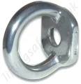
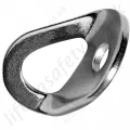
The AM211 Protecta Fixed Anchorage Point is corrosion resistant stainless steel anchor point rated for a single user in two directions. It installs in steel structures with an M12 A2 or A4 class bolt, or in masonry with an M12 chemical resin fastener.
The Fixed Anchorage Point is a single point fall arrest anchor tested to, and in conformance with EN795 Class B. It can serve as the anchorage point(s) for a lanyard. The Fixed Anchorage Point allows the user full freedom in the work zone while securely connected to a safety system. Users should attach to the Fixed Anchorage Point via a energy absorbing lanyard attached to a full body harness.
- Can be used as an anchorage point for Fall Arrest, Positioning, Suspension, and Fall Restraint systems.
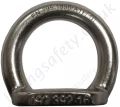
- Made from AISI 316 stainless steel.
- Net weight : 110g.
- Conformity with EN 795 class B.
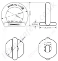
- Dimensions: See 'AM211 Anchorage Point Dimensions' Image above.
Capacity
The maximum number of persons that can be connected to the Fixed Anchorage Point for Fall Arrest purposes is one (1) user.
Applied Loads
The AM211 EN795 Anchorage Point Loading Directions Image below shows correct and incorrect loading directions for the Fixed Anchorage Point.
Loads should always be applied in directions parallel to the anchor faces and never perpendicular to the anchor faces.
The Fixed Anchorage Point is designed for use with systems that limit applied arrest loads to 6 kN or less. Static loads must not exceed 272 kg. Only one person can be attached to the Fixed Anchorage Point. Attachment of two PPE systems by a single user is prohibited.
Installation
Installation of the Fixed Anchorage Point must be performed by competent person(s) familiar with the Fixed Anchorage Point.
Anchorage Structure
The structure to which the Fixed Anchorage Point is mounted must be capable of sustaining 12 kN of force in the anticipated direction(s) of loading (see below). Each Fixed Anchorage Point location must be capable of sustaining this load.
| AM211 EN795 Anchorage Point Loading Directions |
 |
Plane of Anchorage Surface
If the Fixed Anchorage Point is to be installed on a surface that is not perpendicular to the user walking level (e.g., curved or inclined roof, narrow ledge at head height), or a curved surface perpendicular to the user walking level (e.g., silo or vat), consult Capital Safety prior to installation.
Installation Height
The Fixed Anchorage Point may be installed at any practical height above the work surface.
Restraint Systems
Where possible, installations should be designed as a restraint application. Restraint systems prevent the user from reaching a position where a fall can occur; therefore, no free-fall is possible.
Fall Arrest Systems
When the Fixed Anchorage Point is used in a Fall Arrest system, it is important to consider the following factors during design
- Anchorage Point - Mount the anchor as high as possible in relation to the user. This minimizes possible free fall, making rescue easier and less distressing for the victim. Avoid anchor locations that increase the chance of swing fall. Swing falls occur when the anchorage point is not directly above the point where a fall occurs. The force of striking an object in a swing fall may cause serious injury or death. Minimize swing falls by working as close to the anchorage point as possible.
- Anchor Orientation - The Fixed Anchorage Point must be correctly oriented to support the loads applied by the system (see above image).
- Hazards - The work area and path below should be free of any hazards (vehicles, fences, balconies, pedestrians, water/chemicals, etc.) that could injure the user or others if a fall occurs.
Fastening Requirements
- The Fixed Anchorage Point is installed with M12 fasteners:
- Install in metal with an M12 A2 or A4 Class Stainless Steel Bolt.
- Install in masonry with an M12 Adhesive Anchoring System (Hilti HIT-HY 150 or equivalent). Follow the manufacturer’s instructions for installing the Adhesive Anchoring system.
- A Locking Nut and Washer must be used in all installations. All fasteners should be tightened to the fastener manufacturer’s torque recommendations.
- Attach the included Installation Label to the Fixed Anchorage Point after installation.
Proof Load Testing
After installation, the Fixed Anchorage Point must be proof loaded. Using a tension tester, apply a 5kN load for at least 15 seconds in a direction perpendicular to the mating surface. There should be no pull out from the installation structure or deformation of the Fixed Anchorage Point eye.