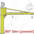
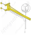
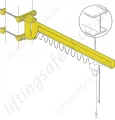
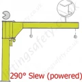
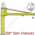
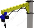
The jib cranes are available in the CBE "Column" version or MBE "Wall" version.
Created for handling goods in areas which are difficult to reach and for lifting big capacities.
Available in standard versions for lifting capacities from 250 kg to 2000 kg.
Jibs from 2m to 8m.
Maximum rotation field 300 for the column version and 270 for the wall version.
Available in "T" cantilever version, which allows the optimal use of the available space at a height and in "H" overbraced version that allows the use of the jib crane for lifting capacities and ranges superior to those of the "T" version.
The rotation mechanism is formed by a motor reducer fixed vertically in the lower part of the support bracket and the drive sprocket of the motor reducer fits together with a toothed crown integral with the arm which it powers.
The progressive starting up and braking are ensured by a variaton of frequency (inverter).
The fixing system for jib crane in the column version is made with base plate, foundation frame and plinths or with counterplate and chemical bolts and the fixing system for wall version is made with bracket and staybolts uni.
Dimensions
| Type |
Lifting Capacity (kg) |
Arm (S) (m) |
Size of Jib Crane |
Total Height (H) m |
Under Beam |
Overall Dimensions |
Speed of Arm |
Motor Power |
Weight |
| |
|
|
|
Base |
Max |
h1 |
h2 |
G |
M |
N |
T |
Δ |
R.P.M |
Peripheric m/min |
KW |
Crane (kg) |
Column by m |
| EH35U60 |
250 |
6 |
U |
3.5 |
5.5 |
2780 |
2250 |
436 |
190 |
1080 |
200 |
17 |
0.6 |
23 |
0.4 |
420 |
43.5 |
| EH35U70 |
7 |
U |
3.5 |
5.5 |
2780 |
2250 |
436 |
190 |
1200 |
152 |
17 |
0.6 |
26 |
0.4 |
507 |
43.5 |
| EH35V80 |
8 |
V |
4 |
6 |
3022 |
2492 |
463 |
190 |
1210 |
152 |
20 |
0.6 |
30 |
0.4 |
765 |
64 |
| EH35U40 |
500 |
4 |
U |
3.5 |
5.5 |
2780 |
2250 |
436 |
190 |
960 |
200 |
17 |
1 |
25 |
0.4 |
370 |
43.5 |
| EH35U50 |
5 |
U |
3.5 |
5.5 |
2780 |
2250 |
436 |
190 |
1020 |
200 |
17 |
0.8 |
25 |
0.4 |
395 |
43.5 |
| EH40V60 |
6 |
V |
4 |
6 |
3022 |
2492 |
463 |
190 |
1090 |
200 |
20 |
0.6 |
23 |
0.4 |
600 |
64 |
| EH40V70 |
7 |
V |
4 |
6 |
3022 |
2492 |
463 |
190 |
1210 |
152 |
20 |
0.6 |
26 |
0.4 |
720 |
64 |
| EH40Z80 |
8 |
Z |
4 |
6 |
3022 |
2492 |
513 |
190 |
1210 |
152 |
20 |
0.6 |
30 |
0.4 |
850 |
75.2 |
| EH40V40 |
1000 |
4 |
V |
4 |
6 |
3022 |
2492 |
463 |
190 |
970 |
200 |
20 |
1 |
25 |
0.4 |
538 |
64 |
| EH40V50 |
5 |
V |
4 |
6 |
3022 |
2492 |
463 |
190 |
1030 |
200 |
20 |
0.8 |
25 |
0.4 |
570 |
64 |
| EH40Z60 |
6 |
Z |
4 |
6 |
3022 |
2492 |
513 |
190 |
1090 |
240 |
20 |
0.6 |
23 |
0.4 |
737 |
75.2 |
| EH40Z70 |
7 |
Z |
4 |
6 |
3022 |
2492 |
513 |
190 |
1210 |
152 |
20 |
0.6 |
26 |
0.4 |
805 |
75.2 |
| EH40Z85 |
8 |
Z |
4 |
6 |
3022 |
2492 |
513 |
190 |
1210 |
152 |
20 |
0.6 |
30 |
0.4 |
850 |
75.2 |
| EH40Z67 |
1600 |
6 |
Z |
4 |
6 |
3022 |
2492 |
513 |
210 |
1170 |
152 |
20 |
0.6 |
23 |
0.4 |
767 |
75.2 |
| EH40Z40 |
2000 |
4 |
Z |
4 |
6 |
3022 |
2492 |
513 |
210 |
990 |
240 |
20 |
0.8 |
20 |
0.4 |
660 |
75.2 |
| EH40Z50 |
5 |
Z |
4 |
6 |
3022 |
2492 |
513 |
210 |
1050 |
240 |
20 |
0.6 |
20 |
0.4 |
697 |
75.2 |