LIFTING
SAFETY
sales@liftingsafety.co.uk
+44 (0)1977 684 600
- Lifting Equipment
-
Height Safety

Height Safety Equipment
- Material Handling & Jacking Equipment
- Shop by Brand
- Clearance
-
Contact
Get In Touch
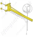
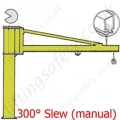
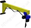
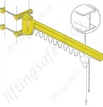
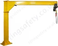
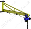
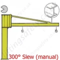
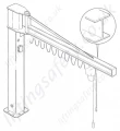
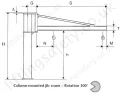
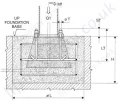
Donati GBA H3 'I' Profile Overbraced Jib Crane - upto 2000kg SWL
300° Manual Slew 'I' Profile Free Standing Swing Jib Crane with Over-braced Arm.
Model:
Donati GBA H3 / PBUT2-979

More from: