
- Lifting Equipment
-
Height Safety
Height Safety Equipment
- Material Handling & Jacking Equipment
- Shop by Brand
- Clearance
-
Contact
Get In Touch
- Home/
- Lifting Equipment/
- General Industrial Lifting Equipment/
- Lifting Clamps (Lifting & Pulling Applications)/
- Steel Section Lifting Clamps/
- Steel Beam Girder lifting / Suspension Clamps, UB, RSJ, "I" Section, "H" Beam./
- Tractel Steel Beam Lifting / Suspension Clamps - To Suit UB, RSJ, I Section or H Section/
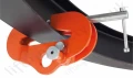
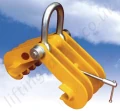
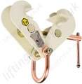
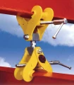
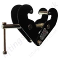
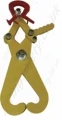
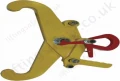
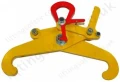
- Tractel TOPAL PL Girder Clamp
These grabs are designed to be used in pairs with a lifting beam.
These accessories are fitted with an open position locking system allowing to lay down the load without any intervention on the clamp.
Functioning
Place the clamp locked open over the profile. Lift up the lever while starting off the lift and hold it in the up position to prevent from locking again against the fastening screw. Lifting ensures proportional clamping, thus minimising load marking. When laying down, the clamp automatically locks itself open. Handles make the positioning easier.
Instructions For Use
- Positioning: suspend the grab in its open position by its ring (1) (locking pawl (2) activated).
- For lifting: present the grab vertically to the product to be lifted.
- Lower the lifting beam and grab assembly until the grabs are applied against the product to be lifted.
- Swivel the locking pawl (2) manually whilst starting off the lifting operation, keep them in the up position to prevent then from locking onto their fastening screw (3).
- Release the locking pawls (2) of each grab making sure that the claw is well above the fastening screw (3) then perform lifting.
- When laying down, lower the lifting beam and grab assembly until the locking pawls are automatically locked (2) onto the fastening screw (3).
- The grabs are locked in the open position, the lifting beam and grab assembly can be lifted up ready to be used again
Dimensions & Specifications

Model | Capacity (kg) | Opening (mm) | Weight (kg) | A | B Handle | B | C | D | E | F | G | H | I | J | K Min Opening | ||||
Min | Max | Min | Max | Min | Max | Min | Max | ||||||||||||
PL1 95-200 | 1000 | 95-200 | 4 | 182 | 348 | 166 | 174 | 73 | 135 | 284 | 504 | 18 | 52 | 69 | 12 | 95 | 22 | 230 | 46 |
PL2 120-300 | 2000 | 120-300 | 8 | 196 | 462 | 167 | 176 | 76 | 140 | 348 | 604 | 23 | 64 | 80 | 20 | 119 | 50 | 330 | 30 |
PL3 180-450 | 3000 | 180-450* | 16 | 296 | 627 | 200 | 205 | 102 | 182 | 435 | 768 | 36 | 74 | 92 | 25 | 143 | 61 | 420 | 23 |
PL4 120-300 | 4000 | 120-300 | 14 | 196 | 444 | 173 | 176 | 75 | 139 | 398 | 622 | 36 | 74 | 92 | 25 | 147 | 74 | 310 | 30 |
*PL3: for each profile >420mm, the clamp must be inserted from the end of the beam.
You May Also Like
Contact Us About This Product
If you wish to receive a quote for this product, please use the tab above, this form is for general enquiries regarding this product only.
You can also Request a Quote using the Quote tab above!
You can easily add more than one item to the Quote Request. This is highly recommended as we will be able to suit your needs much more efficiently.