LIFTINGSAFETY

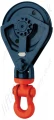
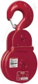
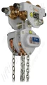
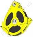
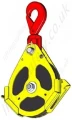
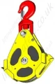
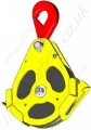
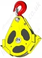
Tractel "EP Series" EN 1808 Man-Riding Pulley Blocks / Snatch Blocks, WLL Range from 1600kg to 4800kg

Wire rope snatch blocks certified for both man-riding and materials handling applications. Various suspension options.

Model: 

EP Series / MRPS-4452


The EP series of man-riding sheaves are the only EN1808 approved sheave blocks available on the market.

Applications

  • EPA/EPC/EPE/EPF/EPL pulleys are designed for man riding applications.
  • Conforms to EN1808.
  • Can also be used for material lifting.
  • Primarily designed for temporary cable lifting or pulling applications, when quick installation and/or removal of the pulley is necessary.
  • Can be fixed to a mobile or fixed anchorage point having the required WLL.
  • Compatible with Tractel hoists.
  • Shaves are made of black polyamide and flanges of S690Q steel.
  • Colors: yellow / red / black.

Casing

  • Protection of hand and fingers against trapping in the pulley groove, as required by EN 1808
  • Stop detection limit for equipped hoists. Stop detection is a requirement of EN 1808 for man riding installations.
  • The casings’ geometry allows using the pulley as opening pulley and facilitating wire-rope positioning.

Suspension Options

  • The EPC and EPF pulleys are equipped with a safety locking hook.
  • The EPE and EPL pulleys are equipped with a hook with safety latch
Epa  Epc Epe Epf Epl
 EPA - Axis Only (for reduced spaces) EPC - Swivel Self Locking Hook EPE - Swivel Sling Hook  EPF - Fixed Self Locking Hook EPL - Fixed Sling Hook

Technical characteristics

  • Ultimate load is 4 times the working load limit (WLL).
  • The EP snatch block has been designed according to FEM 87 and EN 1808 regulations.
  • The EP snatch block comes with a polyamide (PA6G) sheave and a steel body (S690 Q).

Dimensional Specifications

EP Pulleys exist in three models, with three different anchoring systems:

  • EPA equipped with an axis for reduced space installation;
  • EPC equipped with a swivel safety locking hook;
  • EPE equipped with a swivel hook with safety latch
  • EPF equipped with a fixed safety locking hook
  • EPL equipped with a fixed hook with safety latch
Model Head Fitting Sheave Dia. BOG* (mm) Sheave Dia. Exterior (mm) Wire Rope Dia. (mm) WLL (kg) Weight (kg)
EPA1.6-8/9 Axis 172 198 8-9 1600 2.9
EPA2.4-10/12 Axis 196 219.5 10-12 2400 5
EPA4.8-14/16 Axis 277.4 310.7 14-16 4800 12.2
             
EPC1.6-8-9 Swivel Self Locking Hook 172 198 8-9 1600 3.7
EPC2.4-10/12 Swivel Self Locking Hook 196 219.5 10-12 2400 6.4
EPC4.8-14/16 Swivel Self Locking Hook 277.4 310.7 14-16 4800 14.8
             
EPE1.6-8/9 Swivel Sling Hook 172 198 8-9 1600 3.7
EPE2.4-10/12 Swivel Sling Hook 196 219.5 10-12 2400 6.4
EPE4.8-14/16 Swivel Sling Hook 277.4 310.7 14-16 4800 14.8
             
EPF1.6-8/9 Fixed Self Locking Hook 172 198 8-9 1600 3.5
EPF2.4-10/12 Fixed Self Locking Hook 196 219.5 10-12 2400 5.9
EPF4.8-14/16 Fixed Self Locking Hook 277.4 310.7 14-16 4800 14.1
             
EPL1.6-8/9 Fixed Sling Hook 172 198 8-9 1600 3.5
EPL2.4-10/12 Fixed Sling Hook 196 219.5 10-12 2400 5.9
EPL4.8-14/16 Fixed Sling Hook 277.4 310.7 14-16 4800 14.1

* BOG = Bottom of Groove

Safety warnings

  • Strictly forbidden to either be under or to walk under the load.
  • Never use this block for a load exceeding its Working Load Limit (WLL). The WLL is written on the block.
    Shock loading or specific conditions must also be taken into consideration when determining the product to be used.
  • The block should be regularly inspected (priory checking: parts correctly assembled, no excessive movement, no excessive wearing or corrosion, no deformation, no weld corrosion or cracking, free rotation of the sheave).
  • Prior to using the block, check for proper position and locking of the axles. Threaded axle head should be visible after application of nuts.
  • Never use a block with a hook (EPF, EPE, EPL or EPC) as head fitting without ensuring that the safety latch is correctly operated and in good condition.
  • For lifting operations, the user must refer to the safety rules and regulations applicable to this use.

Suspension Effort

Maximal effort applied on the head fitting of the block

The maximal effort applied on the suspension depends on the load and on the α angle formed between the fall of the load and the fall on which this effort is applied.

The resultant value:

  • Must be strictly lower than the working load limit of the block
    and
  • Must be strictly lower than the resistance of the anchorage point where the block is fitted

Please refer to the table and sketch hereunder indicated:

α angle Effort applied on the suspension
Winch WLL x 2
15° Winch WLL x 1.98
30° Winch WLL x 1.95
45° Winch WLL x 1.85
60° Winch WLL x 1.73
90° Winch WLL x 1.41
120° Winch WLL x 1
150° Winch WLL x 0.52
180° 0


Installation

The pulley’s new design allows for easier installation.

Installation 1 1. Remove the axis, shift the brace and install the cable.
Installation 2 2. Put the brake back in place; place the axis (and the hook if the pulley is equipped with a hook).
Installation 3 3. Fit the cable inside the carter through the opening. (This operation can also be done before re-installing the axis)

Optional Remote Installation

It is possible to install the pulley at a distance:

  • Replace the security hook by a standard hook with safety latch (EPC > EPE, EPF > EPL)
  • Add a threaded cap in order to insert a pole (group code 106697, sold by TSAS).

This solution is sold as a kit (designation EP-MCP, group code 192969) including threaded cap, threaded pole end, screws & bolts.

When ordered along with a pulley, it is delivered installed on the pulley.

Remote Installation
 

Optional Limit Detection Stop

Depending on the type of stop limit that is being used, the gear-casing cannot always activate the limit detection stop.
In this case, Tractel Solutions suggests an additional stop system which has to be installed onto the wire-rope while assembling the material.
Limit Detection Stop
New Man-Riding EP Pulleys Tech Sheet.pdf

Technical Datasheet

Full technical datasheet for the Tractel EP series pulley blocks
(approx. 0.3Mb)
Part N° Model Head Fitting Sheave Dia. BOG (mm) Sheave Dia, Exterior (mm) Wire Rope Dia. (mm) WLL (kg) Weight (kg) Unit Price Quantity
4452-T26691
192789
EPA1.6-8/9 Tail Board 172 198 8-9 1600 2.9 £  442.00
4452-T26692
192819
EPA2.4-10/12 Tail Board 196 219.5 10-12 2400 5 £  579.00
4452-T26693
192849
EPA4.8-14/16 Tail Board 277.4 310.7 14-16 4800 12.2 £  875.00
Add to Quote Basket   ?  

Contact Us About This Product

LiftingSafety uses cookies to improve your user experience,
To accept this, please click the 'accept' button below.

Top