Donati DRH series wire rope hoists, the most reliable and safe way of lifting.
Introduction to the DRH Electric Hoist
It guarantees maximum safety in hoisting from 800kg up to 40000kg. The competence and experience in design and production, the quality of components used, the high technology employed in the production of mechanical parts, in the finish and in surface treatments as well as the certified quality system UNI EN ISO 9001:2000 which regulates all the company’s activity, allow us to offer a product in line with the most modern international regularity standards.
The DRH electric rope hoist ensures use in a wide range of situations, reliability over time and safety in all operative phases.
The special hydro-repellent finish, obtained by an electrostatic process, guarantees long life and consistency in performance even in particularly hostile environments.
Donati offers a 3-year guarantee on the DRH series of wire rope hoist, starting from the date of delivery, all at a reasonable price.
Electric Wire Rope Hoist and Trolleys
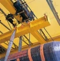
The hoist combined with a trolley which runs on one or two beams also allows horizontal movements. All lifting (raise and lower) and traverse (right and left) movements are activated electrically and can be activated via a fixed pendant, a radio-control system or infra red.

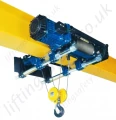
Single Beam Wire Rope Hoist

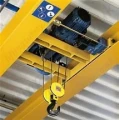
Electric Travel Twin Beam Trolley

Electric Motor - Power and Safety
Basic Range
The range of Donati DRH series electric wire rope hoists has been developed in:
4 basic sizes
- DRH 1-2-3-4, to lift from 800kg to 40 tonnes, including 1020 standard executions, in the FEM service group (ISO), 1Am (M4) – 2m (M5) – 3m (M6).
With one lifting speed made with a 4 pole motor
- 4 or 6 m/min. for 4 rope falls hoists.
- 8 or 12 m/min. for 2 rope falls hoists.
With two speeds made with a 4/12 pole motor
- 4/1,3 or 6/2 m/min. for 4 rope falls hoists.
- 8/2,6 or 12/4 m/min. for 2 rope falls hoists.
With three speeds made with a 4/12 pole motor
- The micro speed is made by frequency control device.
- 5 standard versions with a: short (C), normal (N), long (L) or extra long (X1 and X2) drum lengths, for hook runs from 4 to 58m.
Hoist Suspension Configurations
Fixed configuration
This is the universal, basic configuration, with fixing eyebolts that allow the DRH hoist fixing on a frame as a double girder trolley or in a suspended execution.
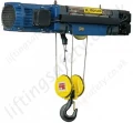
Configuration with monorail trolleys type DST/N/S
The DRH hoist is supplied in suspended execution with the normal headroom trolley or with the articulated one in case the unit has to run on curves. The trolley is electrically operated.
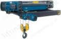
Configuration with monorail trolley type DST/R
In this configuration the DRH hoist is supplied in low eadroom version for a maximum height of lift.
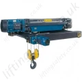
Configuration with double girder trolley type DRT
The DRH hoist can be fitted on the top of the double girder trolley frame or suspended.It can be supplied also in trasversal execution.
The trolley is electrically operated and run on two rails this configuration allows to obtain the maximum hook path (height of lift).
More Information
The DRH series electric wire rope hoists and relative electric trolleys are made with modular components. This allows multiple normalised or special executions to be made quickly, economically but most importantly, safely.
To guarantee maximum use of the hook run and minimum overall dimensions of the hoist body, the base components (motor, reducer and rope drum) are assembled in a coaxial line, by way of high strength bolted connections.
Every connection can be inspected and has self-locking safety nuts. This type of construction, equally as important for the efficiency as for the safety of the hoist, is possible thanks to the extremely compact gear motor unit.
The rope drum on the side opposite the gear motor, can be connected to a cycle counter, selectors, limit switches, encoders, safety brakes etc.
Furthermore, being perfectly symmetrical in the special execution with drum right and left grooved, allows two gear motors to be installed thereby doubling the lifting speed but keeping the same capacity with a true vertical lift. This is a particularly suitable option for executions with large hook runs.
The assembly process uses the most advanced technology and highly industrialised production processes to produce, by economies of scale, totally reliable and technically innovative machines.
Hoist Features
Enclosure and insulation of electrical components
- Hoist and trolley motors: IP55 protection – Class “F” insulation.
- IP23 hoist-motor brake.
- Limit switch: IP65 minimum protection - Maximum insulation voltage 500v.
- Cables: CEI 20/22 II - Maximum insulation voltage 450/750v.
Electric power supply
- DRH electric rope hoists are designed to be supplied with alternate electric current with three-phase voltage: 400 V – 50 Hz, in accordance with IEC 38-1
- Voltage and frequency different from standard are available on request.
Working conditions
- Working temperature: minimum –10°C, maximum +40°C
- Maximum relative humidity: 80%
- Maximum altitude 1000 m above sea level
- The hoist must be installed in a well aired environment free of corrosive vapours (acidic vapours, saline mist, etc.)
Noise levels
- The noise level emitted by a fully loaded hoist is always less than 85 dB (A). However, the transmission of noise through metal structures and the reflection due a machine being located near a wall, are not included in the indicated value.
Hoist Details
1. Electric motor for lifting
Asynchronous three-phase, self-braking with tapered motor. Minimum protection IP 55 – Class F insulation. It has thermal probes for protection against overloading.
2. Hoist’s brake
The brake’s lining is asbestos free. The brake block, which has a fan that guarantees the cooling of the brake itself and of the motor, moves axially with the motor shaft and the braking function is activated automatically if the energy supply fails. (RES. 1.2.6 – 4.1.1.6 c – Attachment I Machine Directive).
3. Joint
It’s the connection between the self-braking motor and the reducer, allowing perfect axial sliding of the motor shaft.
4. Reducer (gearbox)
Coaxial, with three stages of reduction, with cylindrical gears made of thermally treated, highly resistant steel, helicoidal teeth. Dimensioned and made to withstand the phenomena of stress and wear for life in relation to the normal FEM service group. (RES. 4.1.2.3 – Attachment I Machine Directive). The whole machine is mounted on spherical bearingslubricated for life in an oil bath.
5. Drum
The drum in steel casing, is mechanically grooved, and supported by the flange of the reducer and by the equipment side flange, with hubs with rotating broached holes on permanently lubricated bearings. The rope drum is made in line with the ISO standard 4308-1 and UNI 9466 and the FEM rules 9.661/86 and the ratio of the diametral pitch of the same and the diameter of the wound rope is never < 20 (FEM 3m). The rope-drum support flanges have steel cylindrical pins in order to secure the components which suspend the hoist or which support it when set on machined seatings support the anchorage crossheads and the return pulley. The connection between the two flanges is made with bolted staybolts. A protective roof, made of shock-resistant transparent plastic, is fixed above the hoist.
6. Rope guide
It has a threaded ring made of spheroidal graphite cast iron and allows the rope to be wound well onto the drum. [RES.4.1.2.4. – Attachment I Machine Directive]. The system automatically registers any play or wear which may occur. The rope guide includes sliding backlash arms made of brass, which, acting on the staybolts of the hoist, they function as raise and lower limit switches.
7. Raise and lower limit switch
It is a safety component which limits, in an emergency, the run of the hook in raise and lower. [RES. 4.1.2.6. a – Attachment I Machine Directive] There are two micro-switches which work according to the positive slow opening principle and act on the auxiliary circuit of the control device of the hoist’s motor.
8. Pulley assembly
Utilised in versions with more than 2 rope falls, and supported by two pivots which allow it to be orientated depending on the vertical axis of the rope. The return pulley is made of carbon steel. The rim has been grooved mechanically and the sheave rotates on bearings which are permanently lubricated.
9. Anchorage crosshead
Utilised in standard versions, and supported by two pivots which allow it to be orientated depending on the vertical axis of the rope. The overload device is located between the plates of the transverse.
10. Overload device
All the DRH series electric rope hoists have an overload device with a threshold level micro-switch. [RES. 4.2.1.4. – Attachment I Machine Directive]. The overload device constantly measures and checks the values of the load and the dynamic and inertial effects due to its movement. Whenever the set levels is exceeded the micro-switch of the device starts by opening the control circuit of the lifting-controls device.
11. Wedge anchorage
The anchorage is made of spheroidal graphite cast iron. The minimum coefficient for use conforms to the FEM rule 9.661/86. The rope is secured with a wedge which stops it from unwinding.
12. Rope
Made of flexible steel, highly resistant to strain and wear. The minimum coefficient of use has been chosen to conform to the ISO standard 4308-1. Non-twist ropes are used on DRH hoist with 2 falls and long (L) and extra long, 1st size (X1) drums, and on 2 and 4 fall hoists with extra long, 2nd size (X2) drums.
13. Hook block and hook
The return pulley is made of carbon steel and the rim has been grooved mechanically. It rotates on bearings which are permanently lubricated. The load hook is made of highly resistant drop-forged steel and is mounted on an swinging cross beam. It rotates on a thrust bearing and has a safety device to avoid unhooking. [RES. 4.1.2.6 - Allegato I Direttiva Macchine].
14. Frame for electrical connections
Supplied on request. It has cable intake and allows the wiring of all the connections of the electrical equipment of the hoist and electric travel trolley, if present. The compartment for the electrical connections and/or any other low voltage control equipment, is closed with a shock resistant thermoplastic cover, IP 55 enclosure.
15. Low voltage controls
When the hoist is supplied complete with electric controls, the raise and lower and /or right and left functions of the trolley, are activated by electrical equipment which includes:
The transformer for control circuits.
- The main contactor and the contactors/reversing contactor for controlling the motors.
- The fuses for protection of the motors and transformer.
- The terminal board for the connections of auxiliary and power circuits.
The components are mounted on a hinged panel and fixed in a compartment located on the side opposite the motor. The controls are activated by a push-buttons-panel, supplied in AC at low voltage, 48V. The push-buttons-panel is ergonomically shaped, watertight and made of self-extinguishing, shock resistant, thermoplastic material. Its level of protection is IP 65.
The emergency stop [RES. 1.2.4 – Attachment I Machine Directive], is activated by voluntarily pushing the mushroom shaped button, which starts the control circuit [RES. 1.2.3 – Attachment I Machine Directive].
The push-buttons-pannel is connected to the electrical equipment by a multipolar electrical cable with break-resistant metallic cores.
Electric Trolleys
Monorail electric trolley, types DST/N, DST/S and DST/R – Normal, Articulated and Reduced (low headroom)
They are usually composed of an idler wheel and a drive wheel assembly, both have two wheels made of machined pressed steel, and mounted on spherical bearings which are permanently lubricated. The wheels of the drive wheel assembly are opposing and have a crown gear wheel and are connected, in the normal (N) and reduced (R) versions, by a transmission bar. The articulated version (S) has a double motoreducer, both of which directly give the wheels the movement. The steel supporting plates have anti derailment and anti drop device [RES. 4.1.2.2 – Attachment I Machine Directive] and have rubber buffers. Traveling is assured by one or two self-braking motors. They have tapered motor, progressive start up and braking, one or two speeds and one or two offset geared motors with gears with helicoidal teeth which are permanently lubricated in an oil bath.
Electric trolley, normal monorail and standard headroom type DST/N
In the normal version the trolley has supporting bars with circular cross-sections which support the hoist by a hinge-pin type suspension. The drive and idler plates can be adjusted along the bars in relation to the width of the running beam and are complete with brackets which have bolted joints. Both assemblies, drive and idler, are connected to each other with strengthening plates.
Electric trolley, monorail, reduced headroom, type DST/R
In the low headroom version the trolley has supporting bars with circular crosssections which support the hoist in a set-down position. The drive and idler plates are sliding and can be adjusted along the bars, in relation to the width of the running beam, with brackets which have bolted joints. The trolley has a counterbalance on the supporting bar with a circular cross-section in order to balance the eccentric weight of the hoist.
Electric trolley, monorail, articulated, type DST/S
In the articulated version the trolley has supporting bars with circular cross-sections and brackets with hinged joints which support the hoist. The drive and idler plates are sliding and can be adjusted along the bars, in relation to the width of the running beam, with brackets which have bolted joints. Both drive wheel assemblies are opposing on the same bar and are independent from the two idler wheel assemblies.
Electric trolley, double girder, type DRT
The wheels, two of which are driven and two are idler, are supported by a steel crab frame. The wheels, pressed from carbon steel, rotate on permanently lubricated spherical bearings. The double girder trolley has devices to avoid derailment and anti drop [RES. 4.1.2.2 – Attachment I Machine Directive] and rubber buffers.
Activation of traverse is assured by a self-braking motor witht tapered motor, progressive start-up and braking, one or two speeds and one offset reducer with gears with helicoidal teeth which are permanently lubricated in an oil bath, which confer the movement to the drive wheels by a transmission bar. The hoist can be fitted on the top of the trolley or can be suspended and transversal.
Traverse limit switches
On request all trolleys can be supplied complete with the limit switches [RES. 4.1.2.6 a – Attachment I Machine Directive].
Towing arm
A towing arm is available on request for all types of trolleys, adjustable in all directions, to connect the trolley/hoist to the electricity supply and to avoid breakage of the conductors.
Oscillating brackets for hoists mounted on a DST/N trolley.
Available on request to allow the hoist to oscillate with respect to the vertical axis of the running beam.