LIFTINGSAFETY

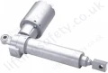
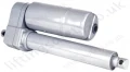
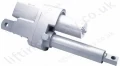
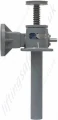
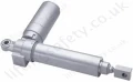
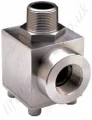
Continuous Duty Cycle Mechanical Screw Jack Actuator

Continuous duty cycle actuator.

Model: 

CDCM-4056


Continuous Duty Cycle Actuators are specifically designed for continuous operation.

The gear set operates in an oil filled bath for thermal efficiency and long life.

The shell is made of a finned aluminium for better cooling properties.

Additionally the ball screw system increases the efficiency of these models.

  • Continuous operation (at rated capacities only).
  • Increased predictable life.
  • High mechanical and thermal efficiency.
  • Oil Lubricated.

Continuous Duty Cycle Upright Rotating Actuator

Continuous Duty Upright Rotating Dimensions
Model Number A B C D E F G H I J K L M N O P Q R S T U V W X Y
UM-7512 7 2 3/4 2.20 6 +.001 1.703 1.12 8.6 4.3 +.000 -.002 .750 +.000-.002 .500 1/2 R 2 1/4 2 3/4 5 1/2 4 1/2 13/32 +.1, 5 1/4 .832 1.13 4.250 3.395 3/4 +.005 2.500 1.171 Dia. .4130 Lead 3.75
UM-7516 8 3/4 2 7/8 2.0 7 +.003-.000 2.589 1 13/16 11 5 1/2 +.000-.002 1.000 +.000-.002 1.000 7/8 R 2 7/8 3 3/4 7 1/2 5 3/4 11/16 +.1, 5 3/4 .895 1 4.937 4.332 1 +.005 2.750 1 1/2 Dia. .474 Lead 4.75
UM-7523 13 3/4 5 1/8 3.75 11 +.005-.000 3.750 2.38 17 7 +.000-.002 1.750 +.000-.002 1.000 1 3/8 R 3 3/4 5 1/8 10 1/4 7 1/2 13/16 +.1, 7 3/4 +0.10 1.582 2 1/4 5.375 +.040 6.706 1 1/2 +.005 3.750 2 1/4 Dia. .500 Lead 8.0

Continuous Duty Cycle Inverted Rotating ActuatorContinuous Duty Inverted Rotating Dimensions

Model Number A B C D E F G H I J K L M N O P Q R S T U V W X Y
DM-7512 7 2 3/4 2.20 6 +.001 1.703 1.12 8.6 4.3 +.000 -.002 .750 +.000-.002 .500 1/2 R 2 1/4 2 3/4 5 1/2 4 1/2 13/32 +.1, 5 1/4 .832 1.13 4.250 3.395 3/4 +.005 2.500 1.171 Dia. .4130 Lead 3.75
DM-7516 8 3/4 2 7/8 2.0 7 +.003-.000 2.589 1.81
11 5 1/2 +.000-.002 1.000 +.000-.002 1.000 7/8 R 2 7/8 3 3/4 7 1/2 5 3/4 11/16 +.1, 5 3/4 .895 1 4.937 4.332 1 +.005 2.750 1 1/2 Dia. .474 Lead 4.75
DM-7523 13 3/4 5 1/8 3.75 11 +.005-.000 3.750 2.38 14 7 +.000-.002 1.750 +.000-.002 1.000 1 3/8 R 3 3/4 5 1/8 10 1/4 7 1/2 13/16 +.1, 7 3/4 +0.10 1.582 2 1/4 5.375 +.040 6.706 1 1/2 +.005 3.750 2 1/4 Dia. .500 Lead 8.0

Continuous Duty Cycle Upright Translating Dimensions

Continuous Duty Upright Translating Dimensions
Model Number Dimensions
A B C D E F G H I J K L M N O P Q* R S T U** V W X Y Z
7511 7 2 3/4 2.20 6 +.001 - .703 1.12 8.6 4.3 3/4-16UNF-2A +.000-.002.500 1/2 R 2 1/4 2 3/4 5 1/2 4 1/2 13/32 +.06 8.4 +.06 8.4 1 1/8 1 21/32 7 O.D. X 4 I.D. 3/4 +.005 2.500 1.171 Dia. .4130 Lead 2 1.5
7515 8 3/4 2 7/8 2 7 + .003 - .000 2.598 1.68 11 5.5 1-14UNS-2A +.000-.002 1.000 7/8 R 2 7/8 3 3/4 7 1/2 5 3/4 11/16 +1 11.2 +.1 9.2 1 1/8 2 3/8 7 O.D. X 4 3/4 I.D. 1 +.005 2.750 1 1/2 Dia. .474 Lead 2 -
7522 13 3/4 5 1/8 3 3/4 11 +.005 - .000 3.750 2.38 14 7.0 1 3/4-12UN-2A +.000-.002 1.000 2 3/8 R 3 3/4 5 1/8 10 1/4 7 1/2 13/16 +1 16.6 +.1 13.2 2 1/4 3 1/2 9.8 O.D. X 6.8 I.D. 1 1/2 +.005 3.750 2 1/4 Dia. .500 Lead 3 -

Continuous Duty Cycle Rotating Screw Actuator Specifications

* Hold back torque is restraining torque at the worm shaft, to keep the load from running down.

Model Number 7512 7516 7523
Max Load Capacity (lbs) 3500 12000 27000
Rated Load Capacity (lbs) 2000 5200 13000
Diameter of Lifting Screw (inch) 1.171 .413 Lead 1.5 .473 Lead 2.250 .50 Lead
Base Sizes (inch) 5 1/2 x 7.0 7 1/2 x 8 3/4 10 1/4 x 13 3/4
Worm Gear Ratio 6:1 8:1 10 2/3:1
Turns of Worm for 1" Raise 14.5 16.888 21.333
Horsepower per Jack (maximum) @ 1750 R.P.M 2 5 10
Starting Torque Max. Load (in-lbs) 75 200 420
Running Torque Max. Load (in-lbs) 60 170 350
Jack Efficiency Rating (%) 70 70 65
Weight with Base Raise of 6" (lbs) 18 42 93
Weight for each Additional 1" Raise (lbs) .42 .85 1.50
Hold Back Torque* at Rated Load (lb-ft) 7 9 12

Continuous Duty Cycle Translating Screw Actuator Specifications

* Hold back torque is restraining torque at the worm shaft, to keep load from running down.

Model Number 7511 7515 7522
Max Load Capacity (lbs) 3500 12000 27000
Rated Load Capacity (lbs) 2000 5200 13000
Diameter of Lifting Screw (inch) 1.171 .413 Lead 1.5 .473 Lead 2.250 .50 Lead
Closed Height (inch) 10 1/4 12 1/4 16 1/2
Base Size (inch) 5 1/2 7.0 7 1/2 8 3/4 10 1/4 13 3/4
Worm Gear Ratio 6:1 8:1 10 2/3:1
Turns of Worm for 1" Raise 14.5 16.888 21.333
Horsepower per Jack (maximum) @ 1750 rpm 2 5 10
Starting Torque Max. Load (in-lbs) 75 200 420
Running Torque Max. Load (in-lbs) 60 170 350
Jack Efficiency Rating (%) 70 70 65
Hold Back Torque* at Rated Load (lb-ft) 7 9 12
Weight with Base Raise of 6" (lbs) 19 43 95
Weight for each Additional 1" Raise (lbs) .42 .85 1.50

Continuous Duty Rotating Actuator Parts List

Continuous Duty Rotating Parts List
Index Number Part Name Quantity
1 Screw, Set (shell cap) 2
2 Shell Cap 1
3 Shell, Actuator 1
4 Bearing, Top & Bottom 2
5 Ball Screw 1
6 Screws, Set (locknut) (7522 model) 1
7 Worm gear 1
8 Gear Extension 1
9 Oil Seal (gear) 2
10 "O" Ring 1
11* Thrustwasher 1
12* Thrustwasher 1
13 Key 1
14 Nut, Lock 1
15 Screw, Cap 8
16 Flange, Worm 2
17 Shim, Flange 2
18 Seal, Oil (worm) 2
19 Worm 1
20 Bearing, Worm 2
21 Oil Plug 3
22 Name Plate 1
23 Plug (7523 Model Inverted) 1
24 Ball Nut & Flange Adaptor Assy. (consists of index numbers, 24A thru 30.) 1
24A** Ball Nut (body) 1
25** Deflector, Yoke As Required
26A** Guide, Ball (used when yoke deflectors are used) As Required
26B** Guide, Ball (used when yoke deflectors are not used) As Required
27** Clamp, Ball Guide As Required
28** Nut, Clamp Fastener As Required
29*** Bearing Balls (only in sets) specify if oversized balls are required)  
30** Flange Adaptor  
31 Guide Bushing (inverted models only) Screw Drive (name plate) 2


Continuous Duty Translating Actuator Parts List

Continuous Duty Translating Parts List
Index Number Part Name Quantity
 1  Screw, Set
 2
 2  Cap, Shell
 1
 3 Shell
 1
 4  Bearing, Load
 2
 5  Pipe, Bottom
 1
 6  Ball Screw
 1
 7  Ball Nut Assembly (Consists of Index Numbers 24 thru 29)
 1
 8  Bearing Retainer
 1
 9  Screw, Set
 3
 10  Worm Gear
 1
 11  Screw, Cap
 1
 12  Washer, Lock
 1
 13  Disc, Retaining
 1
 14  Screw, Hex Head Cap and Washer
 8
 16  Flange  2
 17  Shim, Flange
 2
 18  Seal, Oil
 2
 19  Worm  1
 20  Bearing, Worm
 2
 21  Bushing, Guide (inverted models only)
 1
 22  Oil Plug
 2
 23  Name Plate
 1
 24*  Ball Nut (body)
 1
 25*  Deflector, Yoke
 As Required
 26A*  Guide, Ball (used when yoke deflectors are used)
 As Required
 26B*   Guide, Ball (used when yoke deflectors aren't used)  As Required
 27*  Clamp, Ball Guide
 As Required
 28*  Nut, Clamp Fastener
 As Required
 29**  Bearing Balls, (replace only in set) (specify if oversized balls are required)
1
 30  Sealing Cylinder
 1
 31 Oil Seal  2
 32  "O" Ring
 1
 33  Screw, Set
 3
Continuous Duty Rotating.pdf

Continuous Duty Rotating Actuator Specifications

(approx. 5.4Mb)
Continuous Duty Translating.pdf

Continuous Duty Translating Actuator Specifications

(approx. 4.7Mb)
Custom Dropdown
Part N° Max Load Capacity (lbs) Rated Load Capacity (lbs) Diameter of Lifting Screw (inch) Base Sizes (inch) Worm Gear Ratio Turns of Worm for 1" Raise Weight with Base Raise of 6" (lbs) Weight for each Additional 1" Raise (lbs) Unit Price Quantity
4056-T22720
7512
3500 2000 1.171 .413 Lead 5 1/2 x 7.0 6:1 14.5 18 .42 Quote Required
4056-T22721
7516
12000 5200 1.5 .473 Lead 7 1/2 x 8 3/4 8:1 16.888 42 .85 Quote Required
4056-T22722
7523
27000 13000 2.250 .50 Lead 10 1/4 x 13 3/4 10 2/3:1 21.333 93 1.50 Quote Required
Add to Quote Basket   ?  

Contact Us About This Product

LiftingSafety uses cookies to improve your user experience,
To accept this, please click the 'accept' button below.

Top