User Instructions
1. Reference should be made to German Standards accord.
BGR 500 or other country specific statutory regulations and inspections are to be carried out by competent persons only.
2. Before installing and every use, visually inspect RUD lifting points, paying particular attention to any evidence of weld cracks, corrosion, wear, deformations, etc.
3. The material construction to which the lifting point will be attached should be of adequate strength to withstand forces during lifting without deformation. The contact areas must be free from inpurities, oil, colour, ect.
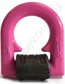
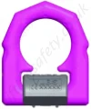
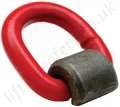
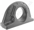
The material of the forged welding block is S355J2+N (St52-3, 1.0577+N), B.S. 4360.50 D or AISI 1019
4. The lifting points must be positioned on the load in such a way that movement is avoided during lifting.
a.) For single leg lifts, the lifting point should be vertically above the centre of gravity of the load.
b.) For two leg lifts, the lifting points must be equidistant to/or above the centre of gravity of the load.
c.) For three and four leg lifts, the lifting points should be arranged symmetrically around the centre of gravity in the same plane.
5. Load Symmetry:
The working load limits of individual RUD lifting points are calculated using the following formula and are based on symmetrical loading:
|
WLL =
|
G
n x cos ß |
WLL = Working Load Limit
G = Load Weight (kg)
n = Number of load bearing legs
ß = Angle of inclination of the chain to the vertical |
The calculation of load bearing legs is as follows:
| No. Legs |
Symmectrical |
Asymmetrical |
| Two Leg |
2 |
1 |
| Three / Four Leg |
3 |
2 |
(See Table 1 and 5)
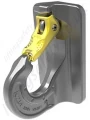
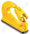
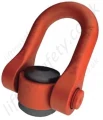
6. All fittings connected to the VLBS should be free moving.
When connecting and disconnecting the lifting means (sling chain) pinches and impacts should be avoided. Damage of the lifting means caused by sharp edges should be avoided as well.
7. The complete design can be annealed stress-free several times up to <600°C (1100°F) without reduction of WLL.
8. The places where the lifting points are fixed should be marked with colour.
9. At outdoor sites or in case of special danger of corrosion, the welds should only be designed as continuous, fillet welds.
The HV weld at the VLBS guarantees a connection via the whole cross section of the material. This corresponds to a closed weld showing no signs of corrosion.
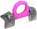
10. The distance lugs assist in achieving the correct root weld (approx. 3 mm = 0.1 inch). They may not be removed.
11. If the lifting points are used exclusively for lashing the value of the working load limit can be doubled. LC = 2 x WLL
12. After welding, an annual inspection or sooner if conditions dictate should be undertaken by a competent person examining the continued suitability. Also after damage and special occurrences.
Inspection criteria concerning paragraphs 2 and 12:
- The lifting point should be complete.
- The working load limit and manufacturers stamp should be clearly visible.
- Deformation of the component parts such as body and load ring.
- Mechanical damage, such as notches, particulary in high stress areas.
- Wear should be no more than 10% of cross sectional diameter.
- Evidence of corrosion.
- Evidence of cracks.
- Cracks or other damages to the welding.
A non-adherence to this advice may result damages of persons and materials !