LIFTING
SAFETY
sales@liftingsafety.co.uk
+44 (0)1977 684 600
- Lifting Equipment
-
Height Safety

Height Safety Equipment
- Material Handling & Jacking Equipment
- Shop by Brand
- Clearance
-
Contact
Get In Touchsales@liftingsafety.co.uk +44 (0)1977 684 600

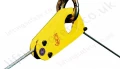
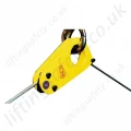
Tractel TOPAL TC Automatic Load Positioner for Single Rope - Range from 2000kg to 5000kg
Automatic load positioner for single wire rope
Model:
TOPAL TC / TTT-3318
More from: