
- Lifting Equipment
-
Height Safety
Height Safety Equipment
- Material Handling & Jacking Equipment
- Shop by Brand
- Clearance
-
Contact
Get In Touch
- Home/
- Lifting Equipment/
- General Industrial Lifting Equipment/
- Lifting Eye Bolts & Nuts/
- Swivel Lifting Eye Bolts/
- Crosby Swivel Lifting Eye Bolts/
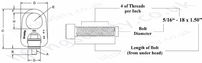
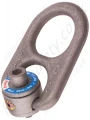
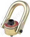
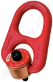
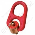
- Crosby 'HR1000M' & 'HR1000' Heavy Duty Swivel Hoist Ring
- Available in both UNC Thread and Metric Thread style
- Forged bail provides the following: Easily readable “Raised Lettering” showing the name Crosby or “CG” and PIC Code for material traceability. Greater durability providing the increased “Toughness” desired in potentially abusive field conditions. Larger opening than standard Hoist Ring bail.
- Top washer is color coded for easy identification (Red for UNC threads and Silver for Metric threads).
- The Working Load Limit and Recommended Torque value are permanently stamped into each washer.
- Individually Proof Tested to 2-1/2 times Working Load Limit.
- Bolt Size Identification: The size of the bolt will be stated as in the drawing below. Illustration shows meaning of each dimension given.
- Frame 2 and larger are RFID EQUIPPED.
HR-1000M with Metric Thread
Frame Size No. |
HR-1000M Stock No. |
Working Load Limit (kg)* |
Torque in Nm |
Dimensions (mm) |
Weight Each (kg) |
||||||||
At a 5:1 Design Factor*** | At a 4:1 Design Factor*** | Bolt Size A |
Eff. Thread Projection Length B |
C | D | Radius E |
Diameter F |
G | H | ||||
1 | 1068307 | 400 | 500 | 10 | M8 x 1.25 x 40 | 15.2 | 93.7 | 24.6 | 15.7 | 11.2 | 57.7 | 35.1 | .3 |
1 | 1068316 | 450 | 550 | 16 | M10 x 1.50 x 40 | 15.2 | 93.7 | 24.6 | 15.7 | 11.2 | 57.7 | 35.1 | .3 |
2 | 1068325 | 1050 | 1300 | 38 | M12 x 1.75 x 55 | 15.5 | 162 | 49.8 | 31.8 | 19.1 | 107 | 63.5 | 1.5 |
2 | 1068334 | 1900 | 2400 | 81 | M16 x 2.00 x 65 | 25.5 | 162 | 49.8 | 31.8 | 19.1 | 107 | 63.5 | 1.5 |
2 | 1068343 | 2150 | 2700 | 136 | M20 x 2.50 x 70 | 30.5 | 162 | 49.8 | 31.8 | 19.1 | 107 | 63.5 | 1.6 |
3 | 1068352 | 3000 | 3750 | 136 | M20 x 2.50 x 80 | 25.4 | 220 | 75.2 | 41.4 | 25.4 | 159 | 82.6 | 4.6 |
3 | 1068361 | 4200 | 5250 | 312 | M24 x 3.00 x 90 | 35.4 | 220 | 75.2 | 41.4 | 25.4 | 159 | 82.6 | 4.8 |
4 | 1068370 | 7000 | 8750 | 637 | M30 x 3.50 x 140 | 66.2 | 285 | 94.2 | 50.8 | 31.8 | 199 | 102 | 9.7 |
4 | 1068389 | 11000 | 13750 | 1005 | M36 x 4.00 x 130 | 56.2 | 285 | 94.2 | 50.8 | 31.8 | 199 | 102 | 10.2 |
*Ultimate Load is 5 times the Working Load Limit.
** Ultimate Load is 4.5 times the Working Load Limit for 7000# Hoist Ring when tested in 90 degree orientation.
***Individually proof loaded to 2-1/2 times the Working Load Limit based on the 4:1 design factor.
Long Bolts are designed to be used with soft metal (i.e. aluminum) work piece. Whilethe long bolts may also be used with ferrous metal (i.e., steel & iron) work piece, short bolts are designed for ferrous work pieces only.
NOTE: The tightening torque values shown are based upon threads being clean, dry and free of lubrication.
HR-1000 UNC Imperial Thread
Frame Size No. |
HR-1000 Stock No. |
Working Load Limit (lbs.) * |
Torque in Ft. Lbs. |
Dimensions (in.) |
Weight Each (lbs.) |
|||||||
Bolt Size A |
Eff. Thread Projection Length B |
C | D | Radius E |
Diameter F |
G | H | |||||
1 | 1068002 | 800 | 7 | 5-16 - 18 x 1.50 | .52 | 3.69 | .97 | .62 | .44 | 2.27 | 1.38 | .60 |
1 | 1068006 | 1000 | 12 | 3/8 - 16 x 1.50 | .52 | 3.69 | .97 | .62 | .44 | 2.27 | 1.38 | .62 |
2 | 1068010 | 2500 | 28 | 1/2 - 13 x 2.25 | .69 | 6.26 | 1.96 | 1.25 | .62 | 4.20 | 2.50 | 3.05 |
2 | 1068014 | 2500 | 28 | 1/2 - 13 x 2.75 | 1.19 | 6.26 | 1.96 | 1.25 | .62 | 4.20 | 2.50 | 3.07 |
2 | 1068018 | 4000 | 60 | 5/8 - 11 x 2.25 | .69 | 6.26 | 1.96 | 1.25 | .62 | 4.20 | 2.50 | 3.11 |
2 | 1068022 | 4000 | 60 | 5/8 - 11 x 3.00 | 1.44 | 6.26 | 1.96 | 1.25 | .62 | 4.20 | 2.50 | 3.18 |
2 | 1068026 | 5000 | 100 | 3/4 - 10 x 2.50 | .94 | 6.26 | 1.96 | 1.25 | .62 | 4.20 | 2.50 | 3.24 |
2 | 1068030 | 5000 | 100 | 3/4 - 10 x 3.00 | 1.44 | 6.26 | 1.96 | 1.25 | .62 | 4.20 | 2.50 | 3.30 |
3 | 1068034 | 7000 ** | 100 | 3/4 - 10 x 3.00 | .85 | 8.66 | 2.96 | 1.63 | 1.00 | 6.25 | 3.25 | 10.09 |
3 | 1068038 | 7000 ** | 100 | 3/4 - 10 x 3.50 | 1.35 | 8.66 | 2.96 | 1.63 | 1.00 | 6.25 | 3.25 | 10.21 |
3 | 1068042 | 8000 | 160 | 7/8 - 9 x 3.00 | .85 | 8.66 | 2.96 | 1.63 | 1.00 | 6.25 | 3.25 | 10.21 |
3 | 1068046 | 8000 | 160 | 7/8 - 9 x 3.50 | 1.35 | 8.66 | 2.96 | 1.63 | 1.00 | 6.25 | 3.25 | 10.40 |
3 | 1068050 | 10000 | 230 | 1 - 8 x 3.50 | 1.35 | 8.66 | 2.96 | 1.63 | 1.00 | 6.25 | 3.25 | 10.50 |
3 | 1068054 | 10000 | 230 | 1 - 8 x 4.50 | 2.35 | 8.66 | 2.96 | 1.63 | 1.00 | 6.25 | 3.25 | 10.72 |
4 | 1068058 | 15000 | 470 | 1-1/4 - 7 x 5.00 | 2.09 | 11.21 | 3.71 | 2.00 | 1.25 | 7.82 | 4.00 | 21.90 |
4 | 1068062 | 24000 | 800 | 1-1/2 - 6 x 5.50 | 2.59 | 11.21 | 3.71 | 2.00 | 1.25 | 7.82 | 4.00 | 23.00 |
*Ultimate Load is 5 times the Working Load Limit.
** Ultimate Load is 4.5 times the Working Load Limit for 7000# Hoist Ring when tested in 90 degree orientation.
***Individually proof loaded to 2-1/2 times the Working Load Limit based on the 4:1 design factor.
Long Bolts are designed to be used with soft metal (i.e. aluminum) work piece. Whilethe long bolts may also be used with ferrous metal (i.e., steel & iron) work piece, short bolts are designed for ferrous work pieces only.
NOTE: The tightening torque values shown are based upon threads being clean, dry and free of lubrication.
You May Also Like
Contact Us About This Product
If you wish to receive a quote for this product, please use the tab above, this form is for general enquiries regarding this product only.
You can also Request a Quote using the Quote tab above!
You can easily add more than one item to the Quote Request. This is highly recommended as we will be able to suit your needs much more efficiently.