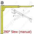
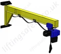
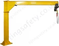
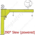
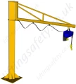
The manually rotated jib cranes with an articulated arm in the CBB "column" series and the MBB "wall" series, are designed for the handling of goods inside the plant where the presence of fixed obstacles would impede the free rotation in terms of the mobility of the arm when it is formed by one rigid element.
The cranes with an articulated jib are fitted with an arm made of two hinged pantograph-shaped segments which allow it to avoid fixed obstacles during rotation. The two semi-arms can be of different lengths and are able to rotate independently of each other.
The standard models are available for lifting capacities from 125 Kg to 500 Kg and jibs from 2 m to 7 m and maximum rotation field of 360. The manually jib cranes are provided with a clutch braking device for the arm which allows the control of the rotation stress.
Dimensions
Type
Lifting Capacity (kg)
Arm (S) (m)
Size of Jib Crane
Height (H) (mm)
Under Beam
Overall Dimensions (mm)
Added Hoist
Weight
Base
Max
h1
h2
h3
S1
S2
G
M
Δ
DMK
Height I
Crane (kg)
Column by m (kg)
A30R3A
125
3
R
3020
5020
2603
2777
2995
1000
2000
228
180
32
1
285
166
18.2
A30R3B
3020
5020
2603
2777
2995
1500
1500
228
180
32
1
285
190
18.2
A30R3C
3020
5020
2603
2777
2995
2000
1000
228
180
32
1
285
212
18.2
A30S4A
4
S
3020
5020
2603
2737
2995
1000
3000
274
180
32
1
285
215
22.8
A30S4B
3020
5020
2603
2737
2995
1500
2500
274
180
32
1
285
237
22.8
A30S4C
3020
5020
2603
2777
2995
2000
2000
274
180
32
1
285
245
22.8
A30S5A
5
S
3020
5020
2603
2737
2995
2000
3000
274
180
32
1
285
272
22.8
A30S5B
3020
5020
2603
2737
2995
2500
2500
274
180
32
1
285
294
22.8
A30S5C
3020
5020
2603
2777
2995
3000
2000
274
180
32
1
285
304
22.8
A35T6B
6
T
3525
5525
3083
3220
3478
2500
3500
323
180
42
1
285
450
35
A35T6C
3525
5525
3083
3220
3478
3000
3000
323
180
42
1
285
485
35
A35T7A
7
T
3525
5525
3083
3200
3478
3000
4000
323
180
42
1
285
513
35
A35T7B
3525
5525
3083
3220
3478
3500
3500
323
180
42
1
285
534
35
A3053A
250
3
S
3020
5020
2603
2737
2995
1000
2000
274
180
32
1-2
285-318
198
22.8
A3053B
3020
5020
2603
2737
2995
1500
1500
274
180
32
1-2
285-318
220
22.8
A35T4A
4
T
3525
5525
3083
3180
3478
1000
3000
323
180
42
1-2
285-318
342
35
A35T4C
3525
5525
3083
3220
3478
2000
2000
323
180
42
1-2
285-318
382
35
A35T5A
5
T
3525
5525
3083
3180
3478
2000
3000
323
180
42
1-2
285-318
419
35
A35T5B
3525
5525
3083
3180
3478
2500
2500
323
180
42
1-2
285-318
448
35
A35U6B
6
U
3525
5525
3083
3180
3478
2500
3500
386
180
42
1-2
285-318
520
43.5
A35U6C
3525
5525
3083
3180
3478
3000
3000
386
180
42
1-2
285-318
552
43.5
A35U7A
7
U
3525
5525
3083
3180
3478
3000
4000
386
180
42
1-2
285-318
577
43.5
A35U7B
3525
5525
3083
3180
3478
3500
3500
386
180
42
1-2
285-318
604
43.5
A35T3A
500
3
T
3525
5525
3083
3220
3478
1000
2000
323
180
42
2
318
306
35
A35T3F
3525
5525
3083
3220
3478
1000
2000
323
190
42
3
385
306
35
A35T3B
3525
5525
3083
3220
3478
1500
1500
323
180
42
2
318
339
35
A35T3G
3525
5525
3083
3220
3478
1500
1500
323
190
42
3
385
339
35
A35U4A
4
U
3525
5525
3083
3180
3478
1000
3000
386
180
42
2
318
390
43.5
A35U4F
3525
5525
3083
3180
3478
1000
3000
386
190
42
3
385
390
43.5
A35U4C
3525
5525
3083
3220
3478
2000
2000
386
180
42
2
318
430
43.5
A35U4H
3525
5525
3083
3220
3478
2000
2000
386
190
42
3
385
430
43.5
A35U5A
5
U
3525
5525
3083
3180
3478
2000
3000
386
180
42
2
318
467
43.5
A35U5F
3525
5525
3083
3180
3478
2000
3000
386
190
42
3
385
467
43.5
A35U5B
3525
5525
3083
3180
3478
2500
2500
386
180
42
2
318
496
43.5
A35U5G
3525
5525
3083
3180
3478
2500
2500
443
190
42
3
385
496
43.5
A40V6A
6
V
4025
6025
3565
3620
3958
2000
4000
443
180
45
2
318
796
64
A40V6F
4025
6025
3565
3620
3958
2000
4000
443
190
45
3
385
796
64
A40V6C
4025
6025
3565
3620
3958
3000
3000
443
180
45
2
318
853
64
A40V6H
4025
6025
3565
3620
3958
3000
3000
443
190
45
3
385
853
64
A40V7A
7
V
4025
6025
3565
3620
3958
3000
4000
443
180
45
2
318
911
64
A40V7F
4025
6025
3565
3620
3958
3000
4000
443
190
45
3
385
911
64
A40V7B
4025
6025
3565
3620
3958
3500
3500
443
180
45
2
318
961
64
A40V7G
4025
6025
3565
3620
3958
3500
3500
443
190
45
3
385
961
64
Oversized Base Plate/CounterPlate (Bolting To Existing Floor)
This is designed to spread the load when bolted to a suitable existing concrete floor. Refer below for manufacturers minimum recommended floor thickness.
Counter Plate Type
R
S
T
U
V
Z
Counterplate Dimensions (mm)
C
400
450
500
600
800
950
S
20
25
25
30
35
45
X
330
195
220
180
182
220
Y / Y1
-
-
-
-
-
240 / 248
Nr x Dia.
4 x 15
8 x 15
8 x 19
12 x 19
16 x 25
28 x 25
Counterplate Weight (kg)
20
31
39
63
139
254
Maximum tilting movement allowed (kNm)
11,8
20,7
31,2
56,7
107,3
164
Type of concrete of the floor: Class Rck minimum (kg/cm2)
C250
C250
C250
C250
C250
C250
Minimum thickness of floor block (mm)
140
170
170
220
220
220
Diameter of hole in the floor (mm)
14
14
18
18
24
24
Depth of the hole of the concrete in the floor (mm)
110
110
125
125
170
170
Clamping torques of the bolts (Nm)
40
40
80
80
150
150
Project resistance of traction of one bolt (kN)
25,3
25,3
40
40
74,6
74,6
The fixing of the column using chemical bolts, needs a scrupulous check of suitability in relation to the type of support flooring.
The suitability checks are the responsibility of the user and must be carried out by expert, qualified technicians who will evaluate the feasibility and formally undertake the relative responsibilities.
Base Plate Specifications
Note: The foundation frame with logbolts, used in the column-mounted version for fixing the column itself to the foundation plinth is supplied on request.
The manually rotated jib cranes with an articulated arm in the CBB "column" series and the MBB "wall" series, are designed for the handling of goods inside the plant where the presence of fixed obstacles would impede the free rotation in terms of the mobility of the arm when it is formed by one rigid element.
The cranes with an articulated jib are fitted with an arm made of two hinged pantograph-shaped segments which allow it to avoid fixed obstacles during rotation. The two semi-arms can be of different lengths and are able to rotate independently of each other.
The standard models are available for lifting capacities from 125 Kg to 500 Kg and jibs from 2 m to 7 m and maximum rotation field of 360. The manually jib cranes are provided with a clutch braking device for the arm which allows the control of the rotation stress.
Oversized Base Plate/CounterPlate (Bolting To Existing Floor)
This is designed to spread the load when bolted to a suitable existing concrete floor. Refer below for manufacturers minimum recommended floor thickness.
Counter Plate Type
R
S
T
U
V
Z
Counterplate Dimensions (mm)
C
400
450
500
600
800
950
S
20
25
25
30
35
45
X
330
195
220
180
182
220
Y / Y1
-
-
-
-
-
240 / 248
Nr x Dia.
4 x 15
8 x 15
8 x 19
12 x 19
16 x 25
28 x 25
Counterplate Weight (kg)
20
31
39
63
139
254
Maximum tilting movement allowed (kNm)
11,8
20,7
31,2
56,7
107,3
164
Type of concrete of the floor: Class Rck minimum (kg/cm2)
C250
C250
C250
C250
C250
C250
Minimum thickness of floor block (mm)
140
170
170
220
220
220
Diameter of hole in the floor (mm)
14
14
18
18
24
24
Depth of the hole of the concrete in the floor (mm)
110
110
125
125
170
170
Clamping torques of the bolts (Nm)
40
40
80
80
150
150
Project resistance of traction of one bolt (kN)
25,3
25,3
40
40
74,6
74,6
The fixing of the column using chemical bolts, needs a scrupulous check of suitability in relation to the type of support flooring.
The suitability checks are the responsibility of the user and must be carried out by expert, qualified technicians who will evaluate the feasibility and formally undertake the relative responsibilities.
Note: The foundation frame with logbolts, used in the column-mounted version for fixing the column itself to the foundation plinth is supplied on request.