LIFTINGSAFETY

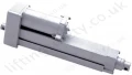
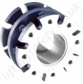
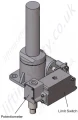
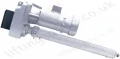
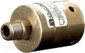
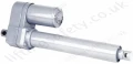
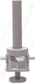
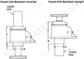
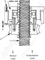
Anti Backlash Machine Screwjack Actuator, 0.25t to 150t

Anti-backlash screwjack actuator.

Model: 

ABMS-4051


Anti Backlash Control

Even the best manufacturing processes produce clearances between a screw and a mating nut.

In applications where loads may be in either direction, backlash can result from these clearances creating unacceptable movement in the controlled mechanism as loads change.

These applications are common in the paper, plastic, film, sheet metal forming processes, satellite, or other load-reversing applications, such applications may be subjected to extreme vibrations.

These vibrations can produce constant movement between the screw and lifting nut which can hammer the threads and cause premature wear.

To reduce this screw-to-nut backlash to an absolute minimum, Anti-Backlash actuators were developed.

The design allows the backlash to be adjusted to the minimum value practical. As wear occurs, the actuator can be easily adjusted, without any disassembly, to return the backlash to its original minimum value.

Key Adaptor Dimensions for Anti-Backlash Actuators

Anti Backlash Ms Dimensions
Actuator Capacity (tons) Upright A Dia. (in) Upright B (in) Upright C (in) Inverted D Dia. (in) Inverted E (in) Inverted F (in)
1/4 & 1/2 1.66 Pipe Length 2.38 1.25 .81 2.88
1 1.66 .75 3.84 1.50 .38 3.38
2 2.25 1.25 3.88 2.25 .63 3.88
3 2.25 1.25 4.34 2.25 .63 4.34
5 2.75 1.75 5.44 2.75 .88 5.44
10 3.38 2.00 5.75 3.38 1.13 5.75
15 3.63 2.00 6.13 3.63 1.25 6.13
20 4.00 1.50 7.75 4.00 1.00 7.75
25 5.50 2.25 9.69 5.50 1.25 9.69
35 6.50 2.38 9.44 6.50 1.25 9.44
50 7.00 3.00 11.75 7.00 3.00 11.75

Anti-Backlash Machine Screw Actuators Performance Specifications

Capacity (tons) 1/4 1/2 1 2 3 5 10 15 20 25 35 50 75 100 150
Max. Speed Cface Driven (in/min)** - - - 72.0 72.0 108.0 108.0 108.0 108.0 107.5 107.5 - - - -
Max. Speed Red. Driven (in/Min)** - - - 14.4 14.14 21.9 21.9 21.9 21.9 22.2 22.4 12.2 - - -
Lifting Screw Diameter (in) 1/2 5/8 3/4 1 1 1 1/2 2 2 1/4 2 1/2 3 3 3/4 4 1/2 5 6 7
Pitch (in) 0.250 0.125 0.200 0.250 0.250 0.375 0.500 0.500 0.500 0.66 0.66 0.66 0.66 0.750 1.000
Type ACME ACME ACME ACME ACME ACME ACME ACME ACME ACME ACME Mod.Sq. Mod.Sq. Mod.Sq. Mod.Sq.
Worm Gear Ratios Standard 5:1 5:1 5:1 6:1 6:1 6:1 8:1 8:1 8:1
10 2/3:1 10 2/3:1 10 2/3:1 10 2/3:1 12:1 12:1
Optional Number 1 - - 20:1 24:1 24:1 24:1 24:1 24:1 24:1 32:1 32:1 32:1 36:1 36:1 36:1
Optional Number 2 - - - 12:1 12:1 12:1 - - - - - - - - -
Turns of Worm for 1" Stroke Standard 20 40 25 24 24 16 16 16 16 16 16 16 16 16 12
Optional Number 1 - - 100 96 96 64 48 48 48 48 48 48 48 48 36
Optional Number 2 - - - 48 48 32 - - - - - - - - -
Worm Torque and No Load (in-lb) Standard 2 2 5 5 5 10 20 20 30 40 50 100 150 200 250
Optional Number 1 - - 5 5 5 10 20 20 30 40 50 100 150 200 250
Optional Number 2 - - 5 5 10 - - - - - - - - - -
Maximum Horsepower per Actuator Standard 1/3 1/3 1/2 2 2 4 5 5 5 8 8 15 15 25 25
Optional Number 1 - - 1/4 1/2 3/4 3/4 1 1/2 1 1/2 1 1/2 2 1/2 2 1/2 6 6 11 11
Optional Number 2 - - - 3/4 1 1/4 2 - - - - - - - - -
Worm Torque Power at Full Load (in-lb) Standard 14 23 61 132 181 495 825 1573 2255 2970 4400 8250 13200 17600 30921
Optional Number 1 - - 28 55 82 204 440 902 1287 1870 2640 4620 7095 9460 17050
Optional Number 2 - - - 82 115 303 - - - - - - - - -
Efficiency Rating (%) Standard 27.8 17.2 21.0 20.1 22.0 20.1 24.1 19.0 17.6 16.7 15.8 12.1 11.3 11.3 12.9
Optional Number 1 - - 11.6 12.1 12.1 12.2 15.1 11.0 10.3 8.9 8.8 7.2 7.0 7.0 7.8
Optional Number 2 - - - 16.1 17.2 16.4 - - - - - - - - -
Weight with 6" Stroke (raise) (lb) 2.3 2.3 5 17 17 35 52 66 93 160 240 410 1200 1200 1350
Weight per Additional 1" Stroke (raise) (lb) 0.1 0.1 0.3 0.3 0.3 0.9 1.4 1.5 2.6 2.5 3.7 5.5 9.0 9.0 12.6
Key Torque (in-lb) 40 70 175 460 670 1750 4700 7580 10625 14000 26500 47110 88650 118200 216000
Max Worm Speed at Full Load (rpm) Standard 1469 909 521 955 696 509 382 200 140 170 115 115 72 90 51
Optional Number 1 - - 573 573 573 232 215 105 73 84 60 82 53 73 41
Optional Number 2 - - - 573 682 416 - - - - - - - - -
Max Load at Full Horsepower and 1750 rpm (lb) Standard 407 474 469 2112 2285 2764 3978 3092 2698 4234 3832 5402 4485 8050 6361
Optional Number 1 - - 356 1041 1705 879 1620 1157 764 1367 1082 2568 1427 4237 2610
Optional Number 2 - - - 1136 2174 2119 - - - - - - - - -

Stainless Steel Anti-Backlash Actuators Performance Specifications

Capacity (tons) - 17-4PH Worm 2 5 10 15 20 25 35 50 100
Capacity (tons) - 316 SS Worm 0.67 1.66 3.33 5.00 6.66 8.33 11.66 16.66 33.33
Lifting Screw Diameter (in) 1
1 1/2
2
2 1/4
2 1/2
3
3 3/4
4 1/2
6
Pitch (in) 0.250
0.375
0.500
0.500
0.500
0.666
0.666
0.666
0.750
Type  ACME ACME
ACME
ACME
ACME
ACME
ACME
Mod.Sq.
Mod.Sq.
Worm Gear Ratios Standard  6:1 6:1
8:1
8:1
8:1
10 2/3:1
10 2/3:1 10 2/3:1  12:1
Optional Number 1 24:1
24:1
24:1
24:1
24:1
32:1
32:1
32:1
36:1
Optional Number 2  12:1 12:1
-
-
-
-
-
-
-
Turns of Worm for 1" Raise Standard  24 16
 16 16
 16 16
 16  16 16
Optional Number 1  96  64 48
48
48
48
48
48
48
Optional Number 2  48 32
-
-
-
-
-
-
-
Worm Torque at No Load (in-lb) Standard 5
10
20
20
30
40
50
100
200
Optional Number 1  5 10
20
20
30
40
50
100
200
Optional Number 2  5 10
-
-
-
-
-
-
-
Maximum Horsepower per Actuator Standard  2 4
5
5
5
8
8
15
25
Optional Number 1  1/2 3/4
1 1/2
1 1/2
1 1/2
2 1/2
2 1/2
6
11
Optional Number 2  3/4 2
-
-
-
-
-
-
-
Worm Torque at Full Load (in-lb) 17-4PH Worm Standard  120 450
750
1430
2050
2700
4000
7500
16000
Optional Number 1  50 185
400
820
1170
1700
2400
4200
8600
Optional Number 2  75 275
-
-
-
-
-
-
-
Worm Torque at Full Load (in-lb) 316SS Worm Standard  43  156  263  490  703 926
1366
2566
5466
Optional Number 1  20 68
147
287
410
593
833
1466
3000
Optional Number 2 28
98
-
-
-
-
-
-
 -
Efficiency Rating (%) Standard  20.4  21.2  25.2  20.3  18.9 17.9
17.0
12.9
12.1
Optional Number 1 11.1
12.1
15.1
11.6
10.8
 9.3 9.3
7.5
7.4
Optional Number 2 15.6 16.8 -
-
-
-
-
-
-
Weight with 6" Raise (lb) 17 35 52 66 93 160 240
410
1200
Weight per Additional 1" Raise (lb) 0.3 0.9 1.4 1.5 2.6 2.5
3.7
5.5
9.0
Key Torque (in-lb) 153
581
1565
2527
3538
4665
8828
15697
39396
Max Worm Speed at Full Load (rpm) Standard 1750 1615
1198
643
449
544
369
368
288
Optional Number 1  1576 694 645
330
231
266
189
258
231
Optional Number 2  1669 1286
-
-
-
-
-
-
-
Max Load at Full Horsepower and 1750 rpm (lb) Standard  1333 3047
4386
3406
2972
4664
4220
5949
8865
Optional Number 1 1156 972
1791
1276
843
1507
1192
2831
4671
Optional Number 2  1258  2339 -
 -  -  -  -  -  -
How Backlash Works

How it Works

When the screw (1) is under a compression load, the bottom of its thread surfaces are supported by the top thread surfaces of the worm gear (2). The anti-backlash nut (3), being pinned to the worm gear and floating on these pins and being adjusted downwards by the shell cap, forcing its bottom thread surfaces against the upper thread surfaces of the lifting screw at point (B).Thus backlash between the worm gear threadsand the lifting screw threads is reduced to a regulated minimum.

When wear occurs in the worm gear threads and the anti-backlash nut thread, the load carrting thickness of the worm gear thread will be reduced. This wear will create a gap at point (B) and provide backlash equal to the wear on the threads.

Under a compression load, the lifting screw will no longer be in contact with the lower thread surface of the anti-backlash nut. Under this condition, backlash will be present when a tension load is applied. The anti backlash feature can be maintained simply by adjusting the shell cap until the desired amount of backlash reduction is achieved. This will reduce the separation (A) between the anti- backlash nut and the worm gear and will reduce the backlash between the worm gear threads and the lifting screw to the desired minimum value.

To avoid binding and excessive wear, do not adjust lifting screw backlash to less than .0005".

When separation (A) has been reduced to zero, the wear limit has been reached.

Replace the worn gear and backlash nut set at this point.

This feature acts as a built in safety device.

Anti-BacklashActuatorsspecifications.pdf

Anti Backlash Actuator Specifications

(approx. 1.4Mb)
Part N° Capacity (tons) Max. Speed Cface Driven (in/min)** Max. Speed Red. Driven (in/Min)** Weight with 6" Stroke (raise) (lb) Weight per Additional 1" Stroke (raise) (lb) Key Torque (in-lb) Unit Price Quantity
4051-T22100 1/4 - - 2.3 0.1 40 Quote Required
4051-T22101 1/2 - - 2.3 0.1 70 Quote Required
4051-T22102 1 - - 5 0.3 175 Quote Required
4051-T22103 2 72.0 14.4 17 0.3 460 Quote Required
4051-T22104 3 72.0 14.14 17 0.3 670 Quote Required
4051-T22105 5 108.0 21.9 35 0.9 1750 Quote Required
4051-T22106 10 108.0 21.9 52 1.4 4700 Quote Required
4051-T22107 15 108.0 21.9 66 1.5 7580 Quote Required
4051-T22108 20 108.0 21.9 93 2.6 10625 Quote Required
4051-T22109 25 107.5 22.2 160 2.5 14000 Quote Required
4051-T22110 35 107.5 22.4 240 3.7 26500 Quote Required
4051-T22111 50 - 12.2 410 5.5 47110 Quote Required
4051-T22112 75 - - 1200 9.0 88650 Quote Required
4051-T22113 100 - - 1200 9.0 118200 Quote Required
4051-T22114 150 - - 1350 12.6 216000 Quote Required
Add To Quote Request   ?  

Contact Us About This Product

LiftingSafety uses cookies to improve your user experience,
To accept this, please click the 'accept' button below.

Top