-
Lifting Equipment

Lifting Equipment
- Chain Hoists
-
Wire Rope Hoists & Winches
- Hand Operated Wire Rope Winches and Hoists
- Cable Pullers / Hoists, Wire Rope Manual Operation
- Electric Winches and Hoists, AC (Mains Powered)
- Scaffold Hoists & Accessories
- Overhead Wire Rope Crane Hoists
- Hydraulic Wire Rope Winches & Hoists
- Pneumatic Wire Rope Air Winches / Hoists (Lifting and Pulling)
- Vehicle Mounted Winches
- Tractel Wire Rope & Accessories
-
General Lifting Equipment
- Soft Lifting Slings
- Lifting Chain Slings
- Wire Rope Slings & Assemblies
- Lifting Shackles
- Eye Bolts and Nuts
- Weld-on Lifting Eyes and Lashing Points
- Lifting & Pulling Clamps
- Lifting Beams & Spreader Beams
- Precast Concrete Lifting
- Lifting Magnets, Permanent, Battery Electric and Manual
- Beam Trolleys and Crane Bridges, Push, Geared & Electric
- Equipment Identification Tags
-
Rigging Equipment
- Master Ring & Load Suspension Eyes
- Lifting & Rigging Hooks
- Turnbuckles & Rigging Screws
- Wire Rope Accessories and Fittings
- Snatch Blocks, Sheave Blocks and Crane Pulley Blocks
- Pulley Sheaves
- Lifting & Rigging Swivels - Eye, Hook & Shackle
- Load Restraint Equipment
- General Rigging Accessories
- Crosby Lifting & Rigging
-
Cranes & Gantry Systems
- Portable Davit Arms
- Swing Jib Cranes - Installed Floor & Wall Cranes
- Portable/Mobile Free-standing Swing Jib Cranes
- Aluminium Gantry Cranes
- Steel Gantry Cranes
- Fixed Steel Gantry Systems
- Shearlegs, Tripods & Quadpods
- Overhead Crane Systems
- Portable Shop-Floor/Workshop/Garage Cranes
- Counterbalance Floor, Workshop Cranes
- Scaffolding Runway Beam Systems
-
Material Handling & Jacking Equipment
- Machinery & Load Moving Skates
- Hydraulic Cylinders & Pumps
- Lifting Jacks
- Manhole Cover Lifters
- Hydraulic Pull Cylinders
- Hand Operated Pallet Trucks, Pump Trucks
- Stacker Trucks, Materials Lifts, Manual and Electric
- Genie and Counterbalance Materials Lifters
- Scissor Lift Tables
- Drum Handling Equipment
- Crane Forks
- Load Weighing Equipment - Load Cells
- Tool Spring Balancers / Load Balancers
- Platform Trucks & Trolleys
-
Forklift Truck Attachment
- Fork Mounted Man Riding Baskets
- Environment & Waste Handling Attachments
- Fork Lift Truck Mounted Drum Handling Attachments
- Fork Mounted Jib and Hook Attachments
- Fork Truck Booms & Tines
- Stainless Steel Forklift Attachments
- Forklift Truck Fork Extensions
- Multi Fork Attachments
- Fork Truck Scoop Attachments
- Big Bag Fork Truck Attachment
- Closed Base Coil Support Attachments
- Forklift Fork Protection Sleeves
- Snow Plough Fork Lift Truck Attachments
- Other Forklift Truck & Telehandler Attachments
- Specialist Lifting Equipment
- Access and Safety Related
- Workshop and Shop Floor
- Screwjacks & Actuators
-
Height Safety

Height Safety Equipment
-
Fall Arrest and Height Safety Harnesses
- General Use Harnesses EN361
- Work Positioning Harnesses EN361 & EN358
- Rope Access Harnesses
- Rescue Harnesses EN1497 & EN361
- Ladies & Childrens Harnesses
- Hi Vis Jacket/Vest Harnesses
- Welders Harnesses
- ATEX (Anti-Static) Harnesses
- Linesman Harnesses
- Oil Derrick Harnesses
- Sport Climbing Harnesses
- Tree Surgeon Positioning Harnesses
- Sit and Chest Harnesses. EN361 EN356 & EN831
- Work Positioning & Restraint Belts EN358
- Fall Arrest, Restraint and Positioning Lanyards
- Height Safety and Fall Arrest Kits
- Inertia Reels and Retrieval Blocks
-
Confined Space and Rescue Systems
- Xtirpa Confined Space Davit Arm Systems and Components
- Sala Advanced Davit Arm Systems and Components
- Genesi Confined Space Systems
- Abtech Man-riding, Fall Arrest and Rescue Davits and Components
- Man-riding Hoists & Rescue Winches
- Fall Arrest & Rescue Tripods
- Fall Arrest Davit Arms & Posts for Working at Height
-
Fall Arrest & Man-riding Systems
- Manriding Systems, Baskets and Chairs
- Mobile Fall Arrest Gantries, Systems & Steps
- Rope Guided Fall Arresters (Steel & Synthetic Rope)
- Temporary Horizontal Fall Arrest Lifelines
- Vertical Fall Arrest Systems Permanently Installed
- Horizontal Fall Arrest Systems Permanently Installed
- Manriding Baskets Fork Truck and Overhead Crane
- Tank Side Entry and Vehicle Fall Arrest Systems
- Suspension Seats / Bosuns Chair Working at Height
- Collective Fall Arrest Systems
- Man-Riding Sheave Blocks
- Anchorage Devices
- Karabiners & Connectors
- Rescue, Evacuation & Rope Access
-
General Height Safety Gear
- Height Safety Accessories
- Industrial & Climbing Height Safety Helmets
- Synthetic Height Safety Rope & Anchorage Lines
- Height safety Pulley Wheels For Synthetic & Steel Wire Rope
- Black Height Safety Equipment & PPE
- Hot Work Equipment. Cutting, Grinding & Welding
- Cases, Bags, Backpacks, Holdalls. Height Safety Gear
- Telescopic Extension Pole for Height Safety Applications
- Wind Energy Height Safety Equipment
- Stainless Steel Fall Arrest Equipment
-
Fall Arrest and Height Safety Harnesses
- Home
- About Us
-
Contact
Get In Touch
Atex Certified Temporary Suspended Access/Man-Riding Platform
2 metre air-driven temporary suspension platform certified for use in explosion proof environments to ATEX II 3G EEx c IIB T3
ALTA A 2m Ex / ASAP-4458
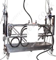
The air-driven ALTA platform «A» has been designed for temporary applications where operators and their work equipment must be lifted to work places at height.
It is perfectly suited to inspection and maintenance work on internal gas tank walls and other places with risk of explosion. Its design allows a certification for use in areas with risk of explosion according to ATEX area II 3G EEx c IIB T3.
Advantages
- Quick access to areas with explosive atmosphere
- Easy maintenance and inspection work at height
- Safe and ergonomic working position
- Rugged structure
- Safe and reliable hoists
- Very low and easy maintenance
- Easy to use
Safety devices
To ensure safe operation without danger to personnel and in accordance with the European standard EN 1808, the platform is fitted with the following safety devices:
... integrated in the TIRAK™ hoists
- Service brake
- Overspeed brake
- Overload safety device
- Manual emergency lowering in case of air pressure loss
... additional safety devices
- EMERGENCY STOP
- 2 BLOCSTOP™ BSA fall arrest devices
- Tilt detection device
- 2 upper limit switches
Main components
Platform
- 2 stirrups: hot dip galvanized steel
- Floor panel: aluminium
- Guard-rail: aluminium
Lifting mechanism
2 TIRAK™ XA-300P traction hoists with pneumatic motor drive (21), equipped with service brake and overload detection.
Suspension wire ropes
Galvanized steel wire ropes, one lifting wire rope (23) and one safety wire rope (24) per suspension point (certified by TRACTEL®).
Fall arrest device
The BLOCSTOP™ BSA fall-arrest device (22) engages on the safety wire rope (24) in the event of a failure on the lifting wire rope (manufactured by TRACTEL®). The BLOCSTOP™ also ensures the detection of a tilting platform.
Air preparation unit
The air preparation unit consists of a filter, a lubricator, a pressure regulator and a manometer. It protects the pneumatic motors and ensures reliable operation and a long life span.
Suspension points (option)
Traversing is ensured by two air-driven monorail trolleys; they can be adapted to I- or H-beam types, beam width 90 to 305 mm.
Controls
The lifting movements are controlled with two control levers (43 and 44) mounted on the guard-rail. Lateral movement of the traversing version is controlled via pendant control boxes.
Variants
| Code | Description |
| 85828 | ALTA <A> platform without traversing |
| 85838 | Two air-driven trolleys suitable for I- or H- beam types, beam with 90 to 305mm |
Technical Specifications
- Overall dimensions (l x w x h): 2,350 x 990 x 2,100 mm
- Internal dimensions of the platform: 2,000 x 600 mm
- Rated capacity: 240 kg
- Lifting speed (m/min): 9 m/min
- Traversing speed: 1-10 m/min (85838 only)
- Min. air pressure: 6 bars
- Air consumption: 3.2 m3/min
- Load per trolley (nominal): 350 daN
Components
Trolleys (optional - 85838)
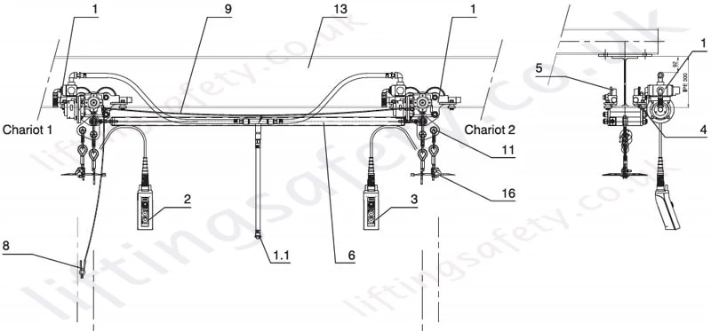
Fig. 1 - Air drive trolleys (option)
1. Air-driven trolley
1.1. Flexible air pressure hose platform - trolley (L = 2 m, 3/4")
2. Pendant control box traversing trolley 1
3. Pendant control box traversing trolley 2
4. Gear for traversing rollers
5. Traversing roller
6. Connecting rod
8. Ground wire cable trolley to platform with clamp (1x 25 mm²)
9. Ground wire cable trolley to trolley without clamp (1x 25 mm²)
11. Tilting suspension stirrup
13. Rail
16. End stop buffer plate
Platform
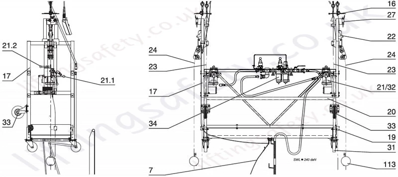
16. End stop buff er plate
17. Stirrup
19. Wire rope guide
20. Guard-rail
21. Air-driven TIRAK™ XA-300P hoist
21.1. TIRAK™ control lever LIFTING / LOWERING
21.2. Brake lever / MANUAL LOWERING
22. BLOCSTOP™ BSA fall arrest device
23*. Lifting wire rope
24*. Safety wire rope
27. Upper limit switch
31. Castor wheel
32. Load limiter integrated in TIRAK™ hoist
33. Facade protection roller
34. Air preparation unit
113. Ballast weight for safety wire rope
* Spare part
Pneumatic Equipment
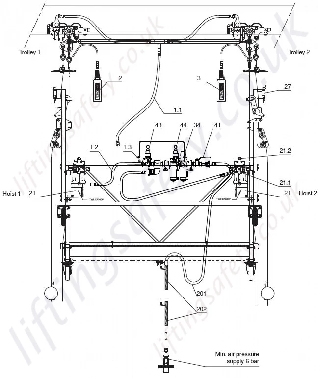
Fig. 3. - Pneumatic Equipment
1.2 Flexible air pressure hose TIRAK™ hoist
1.3 Air pressure connector
2 Pendant control box traversing trolley 1
3 Pendant control box traversing trolley 2
21 Air-driven TIRAK™ XA-300P hoist
21.1 TIRAK™ control lever LIFTING / LOWERING
21.2 Brake lever / MANUAL LOWERING
27 Upper limit switch
34 Air preparation unit
41 Main supply valve / EMERGENCY STOP
43 Control lever LIFTING / LOWERING
44 Control lever LIFTING / LOWERING
201* Flexible air pressure main supply hose (1 1/4")
202 Cable-securing sleeve
* Spare part: set of fl exible air pressure hoses
Pneumatic Diagram
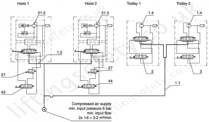
Fig. 4. - Pneumatic Diagram
1.1 Flexible air pressure hose platform - trolley (L = 2 m, 3/4")
1.2 Flexible air pressure hose TIRAK™ hoist
1.4 Air motor for trolley
2 Pendant control box traversing trolley 1
3 Pendant control box traversing trolley 2
21.3* Air motor for TIRAK™ hoist
27 Upper limit switch
43 Control lever LIFTING / LOWERING
44 Control lever LIFTING / LOWERING
Controls
Central air preparation unit
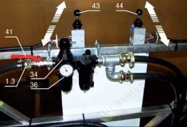
34* Air preparation unit
36 Manometer
41 Main supply valve / EMERGENCY STOP
43 Control lever LIFTING / LOWERING hoist 1
44 Control lever LIFTING / LOWERING hoist 2
Traversing
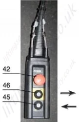
Fig. 6. - Trolley Controls
42 EMERGENCY STOP - traversing
45** Traverse trolley left
46** Traverse trolley right
* Spare part
** Double-speed button
Pricing
Unfortunately, this product has been discontinued and/or is no longer available. Please contact us for details on possible alternative products.
Contact Us About This ProductThe air-driven ALTA platform «A» has been designed for temporary applications where operators and their work equipment must be lifted to work places at height.
It is perfectly suited to inspection and maintenance work on internal gas tank walls and other places with risk of explosion. Its design allows a certification for use in areas with risk of explosion according to ATEX area II 3G EEx c IIB T3.
Advantages
- Quick access to areas with explosive atmosphere
- Easy maintenance and inspection work at height
- Safe and ergonomic working position
- Rugged structure
- Safe and reliable hoists
- Very low and easy maintenance
- Easy to use
Safety devices
To ensure safe operation without danger to personnel and in accordance with the European standard EN 1808, the platform is fitted with the following safety devices:
... integrated in the TIRAK™ hoists
- Service brake
- Overspeed brake
- Overload safety device
- Manual emergency lowering in case of air pressure loss
... additional safety devices
- EMERGENCY STOP
- 2 BLOCSTOP™ BSA fall arrest devices
- Tilt detection device
- 2 upper limit switches
Main components
Platform
- 2 stirrups: hot dip galvanized steel
- Floor panel: aluminium
- Guard-rail: aluminium
Lifting mechanism
2 TIRAK™ XA-300P traction hoists with pneumatic motor drive (21), equipped with service brake and overload detection.
Suspension wire ropes
Galvanized steel wire ropes, one lifting wire rope (23) and one safety wire rope (24) per suspension point (certified by TRACTEL®).
Fall arrest device
The BLOCSTOP™ BSA fall-arrest device (22) engages on the safety wire rope (24) in the event of a failure on the lifting wire rope (manufactured by TRACTEL®). The BLOCSTOP™ also ensures the detection of a tilting platform.
Air preparation unit
The air preparation unit consists of a filter, a lubricator, a pressure regulator and a manometer. It protects the pneumatic motors and ensures reliable operation and a long life span.
Suspension points (option)
Traversing is ensured by two air-driven monorail trolleys; they can be adapted to I- or H-beam types, beam width 90 to 305 mm.
Controls
The lifting movements are controlled with two control levers (43 and 44) mounted on the guard-rail. Lateral movement of the traversing version is controlled via pendant control boxes.
Variants
| Code | Description |
| 85828 | ALTA <A> platform without traversing |
| 85838 | Two air-driven trolleys suitable for I- or H- beam types, beam with 90 to 305mm |
Technical Specifications
- Overall dimensions (l x w x h): 2,350 x 990 x 2,100 mm
- Internal dimensions of the platform: 2,000 x 600 mm
- Rated capacity: 240 kg
- Lifting speed (m/min): 9 m/min
- Traversing speed: 1-10 m/min (85838 only)
- Min. air pressure: 6 bars
- Air consumption: 3.2 m3/min
- Load per trolley (nominal): 350 daN
Components
Trolleys (optional - 85838)

Fig. 1 - Air drive trolleys (option)
1. Air-driven trolley
1.1. Flexible air pressure hose platform - trolley (L = 2 m, 3/4")
2. Pendant control box traversing trolley 1
3. Pendant control box traversing trolley 2
4. Gear for traversing rollers
5. Traversing roller
6. Connecting rod
8. Ground wire cable trolley to platform with clamp (1x 25 mm²)
9. Ground wire cable trolley to trolley without clamp (1x 25 mm²)
11. Tilting suspension stirrup
13. Rail
16. End stop buffer plate
Platform

16. End stop buff er plate
17. Stirrup
19. Wire rope guide
20. Guard-rail
21. Air-driven TIRAK™ XA-300P hoist
21.1. TIRAK™ control lever LIFTING / LOWERING
21.2. Brake lever / MANUAL LOWERING
22. BLOCSTOP™ BSA fall arrest device
23*. Lifting wire rope
24*. Safety wire rope
27. Upper limit switch
31. Castor wheel
32. Load limiter integrated in TIRAK™ hoist
33. Facade protection roller
34. Air preparation unit
113. Ballast weight for safety wire rope
* Spare part
Pneumatic Equipment

Fig. 3. - Pneumatic Equipment
1.2 Flexible air pressure hose TIRAK™ hoist
1.3 Air pressure connector
2 Pendant control box traversing trolley 1
3 Pendant control box traversing trolley 2
21 Air-driven TIRAK™ XA-300P hoist
21.1 TIRAK™ control lever LIFTING / LOWERING
21.2 Brake lever / MANUAL LOWERING
27 Upper limit switch
34 Air preparation unit
41 Main supply valve / EMERGENCY STOP
43 Control lever LIFTING / LOWERING
44 Control lever LIFTING / LOWERING
201* Flexible air pressure main supply hose (1 1/4")
202 Cable-securing sleeve
* Spare part: set of fl exible air pressure hoses
Pneumatic Diagram

Fig. 4. - Pneumatic Diagram
1.1 Flexible air pressure hose platform - trolley (L = 2 m, 3/4")
1.2 Flexible air pressure hose TIRAK™ hoist
1.4 Air motor for trolley
2 Pendant control box traversing trolley 1
3 Pendant control box traversing trolley 2
21.3* Air motor for TIRAK™ hoist
27 Upper limit switch
43 Control lever LIFTING / LOWERING
44 Control lever LIFTING / LOWERING
Controls
Central air preparation unit

34* Air preparation unit
36 Manometer
41 Main supply valve / EMERGENCY STOP
43 Control lever LIFTING / LOWERING hoist 1
44 Control lever LIFTING / LOWERING hoist 2
Traversing

Fig. 6. - Trolley Controls
42 EMERGENCY STOP - traversing
45** Traverse trolley left
46** Traverse trolley right
* Spare part
** Double-speed button
You May Also Like
Contact Us About This Product
If you wish to receive a quote for this product, please use the tab above, this form is for general enquiries regarding this product only.
You can also Request a Quote using the Quote tab above!
You can easily add more than one item to the Quote Request. This is highly recommended as we will be able to suit your needs much more efficiently.

