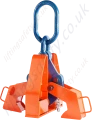
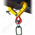
Beam Clamp For the Lifting and Transfer of Wide Flange Beam Sections and Plate Girders
When lifting, these beam clamps grip the beam at three points, and when properly balanced and safely guided, the beam can be handled even if the clamp is slightly off-centre lengthwise.
The Crosby IPBCNS beam clamp is a heavy-duty lifting solution designed for the safe handling and positioning of wide flange beams and plate girders. It features a self-tightening, three-point gripping system that ensures secure and balanced lifting, even when the load is slightly off-centre.
Constructed from high-strength welded alloy steel with forged components, the clamp delivers durability and reliability in demanding industrial environments. It automatically engages under load, increasing clamping force as the weight increases, and eliminates the need for additional rigging such as slings.
Each unit is individually proof-tested to twice its working load limit and comes with full certification, offering confidence in safety and performance for structural steel and construction applications.
Clamp Features
- Capacities: From 13.5 up to 32 metric tonnes (higher Working Load Limits are available upon request).
- Eliminates the need for slings, chokers, and spreader bars.
- When applied to the load, the tongs automatically open and slide under the flange of the beam.
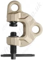
- Centre plate and gripping tongs work together - the heavier the beam, the greater the clamping pressure.
- The base is recessed to accept studs welded to the beam surface.
- Welded alloy steel body for strength and a smaller size. Forged alloy components, where required.
- Individually Proof Tested to 2 times the Working Load Limit with certification.
- Crosby IP logo, Working Load Limit and jaw opening permanently stamped on the body.
- Each product is individually serialised, with the serial number and Proof Load test date stamped on the body. A user manual with a test certificate is included with each clamp.
- Maintenance and repair kits are available.
- Temperature range -40 °C (-40 °F) to +100 °C (+212 °F)
NOTE: Control the beam at all times. Beams should be gripped as near the centre as possible. Snubbing lines at each end must be used to control excessive twisting or swinging, and to guide the beam to its proper place. Each lifting situation may have a specific demand which should be addressed before lifting.
Dimensions & Specifications

| Stock No. |
Base Dimensions (mm) |
| C |
L |
M |
N |
P |
S |
T |
| 2702018 |
444 |
25 |
170 |
112 |
20 |
102 |
62 |
| 2702036 |
596 |
33 |
190 |
170 |
30 |
152 |
92 |
| 2702054 |
730 |
49 |
226 |
203 |
30 |
152 |
92 |
| WLL (t)* |
Stock No. |
Weight (kg) |
Flange Grip Range (mm) |
Dimensions (mm) |
| Width (A) |
Thickness (B) |
C |
D |
E |
F |
G |
K |
| 13.5 |
2702018 |
62 |
178-432 |
13-51 |
444 |
775-749 |
140 |
505-719 |
894-719 |
34 |
| 22.5 |
2702036 |
132 |
406-610 |
25-76 |
596 |
1012-812 |
152 |
775-969 |
1140-982 |
44 |
| 32 |
2702054 |
240 |
406-914 |
41-102 |
730 |
1189-1023 |
178 |
792-1348 |
1458-1258 |
51 |
*Design factor based on EN 13155 and ASME B30.20.