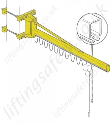
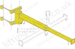
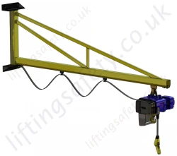
Shopping Basket
Your shopping basket is currently empty
Quote Request Basket
Your quote request basket is currently empty
The manually rotated jib cranes in this series are designed for the handling of goods inside a plant, in a square or to serve operative positions. The standard models are available for lifting capacities from 63kg to 2000kg and jibs from 2m to 8m The C version (this page, see above); T versions and H versions are designed according to the three different versions of the arm.
The column crane can be supplied, on request, with a main on/off line switch which can be padlocked. The distribution of energy takes place via a flat festoon cable which slides on trolley along the arm.
| Lifting Capacity (KG) | Arm (S) Nominal (M) |
True Length (MM) |
Size of Jib Crane Bracket |
Column |
Total Height H (M) Base |
Type |
Under Beam h |
G | L | M | N | Δ | Weight Crane (KG) |
Column by M |
| 63 | 4 | 4056 | A | R | 3 | C30R40 | 2496 | 228 | 34 | 140 | 585 | 12 | 127 | 18.2 |
| 5 | 5056 | A | R | 3 | C30R50 | 2496 | 228 | 34 | 140 | 645 | 12 | 140 | 18.2 | |
| 6 | 6056 | B | S | 3 | C30S60 | 2496 | 274 | 34 | 140 | 705 | 12 | 175 | 22.8 | |
| 7 | 7056 | B | S | 3 | C30S70 | 2496 | 274 | 34 | 140 | 765 | 12 | 188 | 22.8 | |
| 125 | 2 | 2056 | A | R | 3 | C30R20 | 2496 | 228 | 34 | 140 | 525 | 12 | 101 | 18.2 |
| 3 | 3056 | A | R | 3 | C30R30 | 2496 | 228 | 34 | 140 | 585 | 12 | 114 | 18.2 | |
| 4 | 4056 | B | S | 3 | C30S40 | 2496 | 274 | 34 | 140 | 585 | 12 | 149 | 22.8 | |
| 5 | 5056 | B | S | 3 | C30S50 | 2496 | 274 | 34 | 140 | 645 | 12 | 162 | 22.8 | |
| 6 | 6066 | C | T | 3.5 | C35T60 | 2738 | 323 | 34 | 140 | 785 | 17 | 260 | 35 | |
| 7 | 7066 | C | T | 3.5 | C35T70 | 2738 | 323 | 34 | 140 | 845 | 17 | 275 | 35 | |
| 250 | 2 | 2056 | B | S | 3 | C30S20 | 2496 | 274 | 34 | 140 | 525 | 12 | 123 | 22.8 |
| 3 | 3056 | B | S | 3 | C30S30 | 2496 | 274 | 34 | 140 | 585 | 12 | 136 | 22.8 | |
| 4 | 4066 | C | T | 3.5 | C35T40 | 2738 | 323 | 34 | 140 | 665 | 17 | 230 | 35 | |
| 5 | 5066 | C | T | 3.5 | C35T50 | 2738 | 323 | 34 | 140 | 725 | 17 | 245 | 35 | |
| 6 | 6066 | D | U | 3.5 | C35U60 | 2738 | 386 | 43 | 156 | 820 | 17 | 376 | 43.5 | |
| 7 | 7066 | D | U | 3.5 | C35U70 | 2738 | 386 | 43 | 156 | 880 | 17 | 402 | 43.5 | |
| 500 | 2 | 2066 | C | T | 3.5 | C35T20 | 2738 | 323 | 34 | 265 | 730 | 17 | 200 | 35 |
| 3 | 3066 | C | T | 3.5 | C35T30 | 2738 | 323 | 34 | 265 | 790 | 17 | 215 | 35 | |
| 4 | 4066 | D | U | 3.5 | C35U40 | 2738 | 386 | 34 | 265 | 820 | 17 | 287 | 43.5 | |
| 5 | 5066 | D | U | 3.5 | C35U50 | 2738 | 386 | 34 | 265 | 880 | 17 | 303 | 43.5 | |
| 6 | 6076 | E | V | 4 | C40V60 | 2980 | 443 | 43 | 156 | 880 | 20 | 567 | 64 | |
| 7 | 7076 | E | V | 4 | C40V70 | 2980 | 443 | 43 | 156 | 940 | 20 | 597 | 64 | |
| 1000 | 2 | 2066 | D | U | 3.5 | C35U20 | 2738 | 386 | 60 | 306 | 790 | 17 | 267 | 43.5 |
| 3 | 3066 | D | U | 3.5 | C35U30 | 2738 | 386 | 60 | 306 | 850 | 17 | 337 | 43.5 | |
| 4 | 4076 | E | V | 4 | C40V40 | 2980 | 443 | 60 | 306 | 910 | 20 | 509 | 64 | |
| 5 | 5076 | E | V | 4 | C40V50 | 2980 | 443 | 60 | 306 | 970 | 20 | 538 | 64 | |
| 6 | 6076 | F | Z | 4 | C40Z60 | 2980 | 513 | 60 | 306 | 1100 | 20 | 680 | 75.2 | |
| 7 | 7076 | F | Z | 4 | C40Z70 | 2980 | 513 | 60 | 306 | 1160 | 20 | 713 | 75.2 |

Please note that these jibs priced on line are quoted as supply only. We believe that this will give you the most cost effective solution; your engineering staff or a local contractor could install at cheaper hourly rate than our lifting engineers and won't have the travel time that we would incur. If any civil works are required to the floor (or support structure) it would be best (and cheaper) done by Civil Engineering Company (or Fabricator), after all this is their area of expertise. We would be please to offer a price for installation on request.
Or
This is designed to spread the load when bolted to a suitable existing concrete floor. Refer below for manufacturers minimum recommended floor thickness.
| Counter Plate Type | R | S | T | U | V | Z | |
|
Counterplate Dimensions (mm) |
C | 400 | 450 | 500 | 600 | 800 | 950 |
| S | 20 | 25 | 25 | 30 | 35 | 45 | |
| X | 330 | 195 | 220 | 180 | 182 | 220 | |
| Y / Y1 | - | - | - | - | - | 240 / 248 | |
| Nr x Dia. | 4 x 15 | 8 x 15 | 8 x 19 | 12 x 19 | 16 x 25 | 28 x 25 | |
| Counterplate Weight (kg) | 20 | 31 | 39 | 63 | 139 | 254 | |
| Maximum tilting movement allowed (kNm) | 11,8 | 20,7 | 31,2 | 56,7 | 107,3 | 164 | |
| Type of concrete of the floor: Class Rck minimum (kg/cm2) | C250 | C250 | C250 | C250 | C250 | C250 | |
| Minimum thickness of floor block (mm) | 140 | 170 | 170 | 220 | 220 | 220 | |
| Diameter of hole in the floor (mm) | 14 | 14 | 18 | 18 | 24 | 24 | |
| Depth of the hole of the concrete in the floor (mm) | 110 | 110 | 125 | 125 | 170 | 170 | |
| Clamping torques of the bolts (Nm) | 40 | 40 | 80 | 80 | 150 | 150 | |
| Project resistance of traction of one bolt (kN) | 25,3 | 25,3 | 40 | 40 | 74,6 | 74,6 |
The fixing of the column using chemical bolts, needs a scrupulous check of suitability in relation to the type of support flooring.
The suitability checks are the responsibility of the user and must be carried out by expert, qualified technicians who will evaluate the feasibility and formally undertake the relative responsibilities.


Note: The foundation frame with logbolts, used in the column-mounted version for fixing the column itself to the foundation plinth is supplied on request.
| Size of Jib Crane | R | S | T | U | V | Z |
| Base Plate and Foundation Frame (mm) | ||||||
| C | 205 | 258 | 296 | 372 | 435 | 515 |
| P | 275 | 340 | 380 | 475 | 555 | 660 |
| S1 | 15 | 15 | 15 | 20 | 20 | 25 |
| S2 | 8 | 8 | 8 | 8 | 8 | 8 |
| X | 247 | 305 | 345 | 432 | 506 | 599 |
| Y | 103 | 126 | 143 | 179 | 210 | 248 |
| Ø | 268 | 330 | 373 | 468 | 548 | 648 |
| R | 88 | 104 | 116 | 145 | 165 | 197 |
| Ø1 | 16 | 20 | 20 | 25 | 29 | 35 |
| Ø2 | 13 | 17 | 17 | 21 | 25 | 31 |
| Anchorage Bolts | ||||||
| ØT | M12 | M16 | M16 | M20 | M24 | M30 |
| LT | 400 | 450 | 450 | 550 | 600 | 700 |
| ST | 40 | 45 | 45 | 55 | 60 | 75 |
| Clamping Couples (Nm) | 45 | 105 | 105 | 200 | 350 | 680 |
| Frame/Bolts Weight (kg) | 5 | 10 | 11 | 17 | 26 | 47 |
| Foundation | ||||||
| Foundation Plinth (mm) (L) | 1200 | 1300 | 1400 | 1700 | 2000 | 2400 |
| Foundation Plinth (H) | 800 | 800 | 900 | 900 | 1100 | 1100 |
| Reaction (kN) Q1 | 3.3 | 5.7 | 10.15 | 18.4 | 28.7 | 29.35 |
| Momentum (kNm) MF | 10 | 16 | 30 | 56 | 107 | 163 |


If you wish to receive a quote for this product, please use the Pricing section to the right, this form is for general enquiries regarding this product only.
You can also request a quote through the pricing tab!
You can easily add more than one item to the Quote Request. This is highly recommended as we will be able to suit your needs much more efficiently.
The manually rotated jib cranes in this series are designed for the handling of goods inside a plant, in a square or to serve operative positions. The standard models are available for lifting capacities from 63kg to 2000kg and jibs from 2m to 8m The C version (this page, see above); T versions and H versions are designed according to the three different versions of the arm.
The column crane can be supplied, on request, with a main on/off line switch which can be padlocked. The distribution of energy takes place via a flat festoon cable which slides on trolley along the arm.
| Lifting Capacity (KG) | Arm (S) Nominal (M) |
True Length (MM) |
Size of Jib Crane Bracket |
Column |
Total Height H (M) Base |
Type |
Under Beam h |
G | L | M | N | Δ | Weight Crane (KG) |
Column by M |
| 63 | 4 | 4056 | A | R | 3 | C30R40 | 2496 | 228 | 34 | 140 | 585 | 12 | 127 | 18.2 |
| 5 | 5056 | A | R | 3 | C30R50 | 2496 | 228 | 34 | 140 | 645 | 12 | 140 | 18.2 | |
| 6 | 6056 | B | S | 3 | C30S60 | 2496 | 274 | 34 | 140 | 705 | 12 | 175 | 22.8 | |
| 7 | 7056 | B | S | 3 | C30S70 | 2496 | 274 | 34 | 140 | 765 | 12 | 188 | 22.8 | |
| 125 | 2 | 2056 | A | R | 3 | C30R20 | 2496 | 228 | 34 | 140 | 525 | 12 | 101 | 18.2 |
| 3 | 3056 | A | R | 3 | C30R30 | 2496 | 228 | 34 | 140 | 585 | 12 | 114 | 18.2 | |
| 4 | 4056 | B | S | 3 | C30S40 | 2496 | 274 | 34 | 140 | 585 | 12 | 149 | 22.8 | |
| 5 | 5056 | B | S | 3 | C30S50 | 2496 | 274 | 34 | 140 | 645 | 12 | 162 | 22.8 | |
| 6 | 6066 | C | T | 3.5 | C35T60 | 2738 | 323 | 34 | 140 | 785 | 17 | 260 | 35 | |
| 7 | 7066 | C | T | 3.5 | C35T70 | 2738 | 323 | 34 | 140 | 845 | 17 | 275 | 35 | |
| 250 | 2 | 2056 | B | S | 3 | C30S20 | 2496 | 274 | 34 | 140 | 525 | 12 | 123 | 22.8 |
| 3 | 3056 | B | S | 3 | C30S30 | 2496 | 274 | 34 | 140 | 585 | 12 | 136 | 22.8 | |
| 4 | 4066 | C | T | 3.5 | C35T40 | 2738 | 323 | 34 | 140 | 665 | 17 | 230 | 35 | |
| 5 | 5066 | C | T | 3.5 | C35T50 | 2738 | 323 | 34 | 140 | 725 | 17 | 245 | 35 | |
| 6 | 6066 | D | U | 3.5 | C35U60 | 2738 | 386 | 43 | 156 | 820 | 17 | 376 | 43.5 | |
| 7 | 7066 | D | U | 3.5 | C35U70 | 2738 | 386 | 43 | 156 | 880 | 17 | 402 | 43.5 | |
| 500 | 2 | 2066 | C | T | 3.5 | C35T20 | 2738 | 323 | 34 | 265 | 730 | 17 | 200 | 35 |
| 3 | 3066 | C | T | 3.5 | C35T30 | 2738 | 323 | 34 | 265 | 790 | 17 | 215 | 35 | |
| 4 | 4066 | D | U | 3.5 | C35U40 | 2738 | 386 | 34 | 265 | 820 | 17 | 287 | 43.5 | |
| 5 | 5066 | D | U | 3.5 | C35U50 | 2738 | 386 | 34 | 265 | 880 | 17 | 303 | 43.5 | |
| 6 | 6076 | E | V | 4 | C40V60 | 2980 | 443 | 43 | 156 | 880 | 20 | 567 | 64 | |
| 7 | 7076 | E | V | 4 | C40V70 | 2980 | 443 | 43 | 156 | 940 | 20 | 597 | 64 | |
| 1000 | 2 | 2066 | D | U | 3.5 | C35U20 | 2738 | 386 | 60 | 306 | 790 | 17 | 267 | 43.5 |
| 3 | 3066 | D | U | 3.5 | C35U30 | 2738 | 386 | 60 | 306 | 850 | 17 | 337 | 43.5 | |
| 4 | 4076 | E | V | 4 | C40V40 | 2980 | 443 | 60 | 306 | 910 | 20 | 509 | 64 | |
| 5 | 5076 | E | V | 4 | C40V50 | 2980 | 443 | 60 | 306 | 970 | 20 | 538 | 64 | |
| 6 | 6076 | F | Z | 4 | C40Z60 | 2980 | 513 | 60 | 306 | 1100 | 20 | 680 | 75.2 | |
| 7 | 7076 | F | Z | 4 | C40Z70 | 2980 | 513 | 60 | 306 | 1160 | 20 | 713 | 75.2 |

Please note that these jibs priced on line are quoted as supply only. We believe that this will give you the most cost effective solution; your engineering staff or a local contractor could install at cheaper hourly rate than our lifting engineers and won't have the travel time that we would incur. If any civil works are required to the floor (or support structure) it would be best (and cheaper) done by Civil Engineering Company (or Fabricator), after all this is their area of expertise. We would be please to offer a price for installation on request.
Or
This is designed to spread the load when bolted to a suitable existing concrete floor. Refer below for manufacturers minimum recommended floor thickness.
| Counter Plate Type | R | S | T | U | V | Z | |
|
Counterplate Dimensions (mm) |
C | 400 | 450 | 500 | 600 | 800 | 950 |
| S | 20 | 25 | 25 | 30 | 35 | 45 | |
| X | 330 | 195 | 220 | 180 | 182 | 220 | |
| Y / Y1 | - | - | - | - | - | 240 / 248 | |
| Nr x Dia. | 4 x 15 | 8 x 15 | 8 x 19 | 12 x 19 | 16 x 25 | 28 x 25 | |
| Counterplate Weight (kg) | 20 | 31 | 39 | 63 | 139 | 254 | |
| Maximum tilting movement allowed (kNm) | 11,8 | 20,7 | 31,2 | 56,7 | 107,3 | 164 | |
| Type of concrete of the floor: Class Rck minimum (kg/cm2) | C250 | C250 | C250 | C250 | C250 | C250 | |
| Minimum thickness of floor block (mm) | 140 | 170 | 170 | 220 | 220 | 220 | |
| Diameter of hole in the floor (mm) | 14 | 14 | 18 | 18 | 24 | 24 | |
| Depth of the hole of the concrete in the floor (mm) | 110 | 110 | 125 | 125 | 170 | 170 | |
| Clamping torques of the bolts (Nm) | 40 | 40 | 80 | 80 | 150 | 150 | |
| Project resistance of traction of one bolt (kN) | 25,3 | 25,3 | 40 | 40 | 74,6 | 74,6 |
The fixing of the column using chemical bolts, needs a scrupulous check of suitability in relation to the type of support flooring.
The suitability checks are the responsibility of the user and must be carried out by expert, qualified technicians who will evaluate the feasibility and formally undertake the relative responsibilities.


Note: The foundation frame with logbolts, used in the column-mounted version for fixing the column itself to the foundation plinth is supplied on request.
| Size of Jib Crane | R | S | T | U | V | Z |
| Base Plate and Foundation Frame (mm) | ||||||
| C | 205 | 258 | 296 | 372 | 435 | 515 |
| P | 275 | 340 | 380 | 475 | 555 | 660 |
| S1 | 15 | 15 | 15 | 20 | 20 | 25 |
| S2 | 8 | 8 | 8 | 8 | 8 | 8 |
| X | 247 | 305 | 345 | 432 | 506 | 599 |
| Y | 103 | 126 | 143 | 179 | 210 | 248 |
| Ø | 268 | 330 | 373 | 468 | 548 | 648 |
| R | 88 | 104 | 116 | 145 | 165 | 197 |
| Ø1 | 16 | 20 | 20 | 25 | 29 | 35 |
| Ø2 | 13 | 17 | 17 | 21 | 25 | 31 |
| Anchorage Bolts | ||||||
| ØT | M12 | M16 | M16 | M20 | M24 | M30 |
| LT | 400 | 450 | 450 | 550 | 600 | 700 |
| ST | 40 | 45 | 45 | 55 | 60 | 75 |
| Clamping Couples (Nm) | 45 | 105 | 105 | 200 | 350 | 680 |
| Frame/Bolts Weight (kg) | 5 | 10 | 11 | 17 | 26 | 47 |
| Foundation | ||||||
| Foundation Plinth (mm) (L) | 1200 | 1300 | 1400 | 1700 | 2000 | 2400 |
| Foundation Plinth (H) | 800 | 800 | 900 | 900 | 1100 | 1100 |
| Reaction (kN) Q1 | 3.3 | 5.7 | 10.15 | 18.4 | 28.7 | 29.35 |
| Momentum (kNm) MF | 10 | 16 | 30 | 56 | 107 | 163 |


If you wish to receive a quote for this product, please use the tab, this form is for general enquiries regarding this product only.
You can also request a quote through the pricing tab!
You can easily add more than one item to the Quote Request. This is highly recommended as we will be able to suit your needs much more efficiently.
LiftingSafety uses cookies to improve your user experience.
Find out more