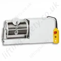
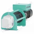
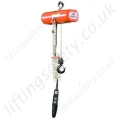
This range of Wind Turbine wire rope hoists are available as 200kg or 300kg SWL with a massive lifting height of upto 120 metres with a choice of lifting speeds, either fixed at 23 metre per minute or adjustable up to 45 metres per minute. We offer single phase 110v, 220v or 3 phase.
This wind turbine hoist is CE Certified and conforms to EEC Machine Directive 89/392 and subsequent amendments. The manufacturer reserves the right to make changes without prior notice and without being subject to any sanctions, and also without affecting the commitment to respect the main safety technical characteristics.
Typical Installation Examples

Hoist mounted over a pulley wheel

Hoist mounted on an articulated jib (Wall or Ceiling mounted)

Hoist mounted to a lightweight run way beam (Two way travel)

Hoist mounted on to a lightweight crane system (Four way travel)
Further Information:
The hoist has been designed and built to lift objects, materials or goods. It is absolutely prohibited to use the machine to lift persons.
The hoist is equipped with an electrical emergency lifting limit switch and it is also designed to install a parking brake on a stand. Self braking motor
The hoist is also equipped with an asynchronous, self-braking motor with a disk brake that is normally blocked by a adequately sized tension springs. The hoist also includes a compact cascade reduction unit.
Standard Features:
- Safety devices: lifting limit switch in conformity with EN50047.
- Hook: Single with anti-release device Capacity 750kg.
- Noise emission: equivalent continuous acoustic pressure level measured under full load according to ISO 3746 (prEN 23746) is 76 dB.
Installation
The hoist can be installed in different ways depending on the type of use. It can be:
- Fitted with a beam trolley (electric or manual) and used on a runway beam.
- Installed onto a swing jib crane (fixed arm or articulating) The Jib can be floor, wall or roof mounted. The roof mounted jib can even be fitted with a beam trolley and used on a runway beam.
- Solid mounted onto a structural steel framework with the wire rope deflected over a pulley wheel.
- In any case, the machine must be anchored and any rotating arms bearing the transmission pulleys must be installed on a stable structure according to the calculations and instructions supplied by a legally qualified technician who must issue a special certificate.
Maintenance:
The entire device is built with class A4 which corresponds to 84000 operating Cycles.
The mechanism are built with class M4 which corresponds to 3200 h of operation. After the number of operating cycles described above, the machine must be overhauled at an authorised service centre.
Instructions for Use
| TECHNICAL DATA |
U.M. |
2639-11902 |
2639-11904 |
2639-11905 |
2639-11907 |
| Electric motor |
Type |
Single-phase |
Three-phase |
Single-phase |
Three-phase |
| Motor power |
kW |
0.9 |
0.95 |
1.9 |
1.5 |
| Voltage |
V |
220 |
380/220 |
220 |
380/220 |
| Frequency |
Hz |
50 |
50 |
50 |
50 |
| Current at peak load |
A |
6.5 |
2.7-4.7 |
10 |
4.3-7 |
| Condenser |
CF |
40 |
- |
60 |
- |
| Max. capacity |
kg |
200 |
200 |
300 |
300 |
| Working length (pull) |
m |
80 |
80 |
80 |
80 |
| Working length (lifting) |
m |
40 |
40 |
40 |
40 |
| Average lifting speed |
m/min |
~20 |
~20 |
~20 |
~20 |
Cable Features
| Hoist |
2639-11902/03/04 |
2639-11905/06/07 |
| Material |
Polished steel |
Polished steel |
| Diameter and composition |
5mm-133 wires |
6mm-133 wires |
| Elementary wire diameter |
0.32 mm |
0.40 mm |
| Wire resistance |
200 kg/mm² |
200 kg/mm² |
| Minimum cable breaking load |
1600 Kg |
2400 Kg |
| Minimum safety coefficient |
8 |
8 |
| Number of bearing sections |
1 |
1 |
Installation Diagrams
For calculation purposes and to verify the stability, the forces acting on the connections under the most severe load condiction are reported in the following table (hoist with a maximum capacity of 200 Kg (ABASPMSPT210) and 300 Kg (ABASPM-SPT300)).
This considers the load acting in the two positions at the ends of the drum and the weight of the hoist itself is neglected.
| Position 1 |
| F |
2639-11902/03/04 |
2639-11905/06/07 |
| (N) |
(kg) |
(N) |
(kg) |
| F1 |
1283 |
131 |
2167 |
221 |
| F2 |
967 |
99 |
1313 |
134 |
| F3 |
210 |
21 |
453 |
46 |
| F4 |
-106 |
-11 |
-402 |
-41 |
| Position 2 |
| F |
2639-11902/03/04 |
2639-11905/06/07 |
| (N) |
(kg) |
(N) |
(kg) |
| F1 |
854 |
87 |
1400 |
143 |
| F2 |
538 |
55 |
545 |
57 |
| F3 |
639 |
65 |
1220 |
124 |
| F4 |
323 |
33 |
366 |
37 |
At the end of the machine anchor operations, the user must ad just the emergency limit switch.
To do this, he must attach the cable tensioning weight (using the special screw) in a position that corresponds to the maximum load lifting height. The weight actson the limit switch lever connected to the machine (see the figure below).
Safety
Check that the lifting limit switch operates correctly at the beginning of each work shift.
The load braking system must be checked every six months and, in any case, each time that, during normal machine use, the load does not stop immediately.
The pendant is protected to IP65 and the machine is built with an IP44 motor; or IP55 if requested.
IP (Ingress Progress) Codes in accordance with IEC 529
- IP44 = 4 - Protected against solid foreign objects of 1.0 mm diameter and greater & 4 - Protected against splashing water
- IP55 = 5 - Dust-protected & 5 - Protected against water jetting
- IP65 = 6 - Dust-tight & 5 - Protected against water jetting
It is also recommended to:
a) avoid overloading the hoist;
b) stop the lifting movement before the limit switch trips since it should only be used in case of emergency;
c) check that the voltage does not decrease excessively during the start-up phase (this may prevent the brake from opening);
Please ensure that the user guide / instructions are complied with fully at all times
The machine must be periodically inspected (on a six-month or yearly basis) to check the general use conditions (e.g. leaking grease, condition of electric power supply cables and machine control components, condition of the support structure, etc.).
In particular:
- The cables must be checked every three months and replaced immediately if there are any breaks in the elementary wires, or if they are twisted, smashed, bent, if knots have formed or if there is any other serious deterioration (heavy rust formation) or if heavily worn.
- The above-mentioned inspections must be reported on a special chart (see appendix page), indicating the date of the inspection and the signature of the tester.
- The braking system must be checked every six months and, in any case, each time that, during normal machine use, the load does not stop immediately.
Instructions for hoist 2639-11903 & 2639-11906 (with adjustable lifting speeds)
(selecting speed - hold button to start hoisting, speed ramps-up to maximum of 45 metres per minute, if slower speeds are required half-release the button to hold that speed.
Operation
The hoist is controlled by means of its dedicated push button control unit, which is fitted with the following buttons and indicators:
- Two push buttons for operation (ascent and descent).
- An emergency push button.
- A speed selection switch.
- A warning light.
- Turn the starter knob to position 1 (ON).
- Check that the green warning light, located at the bottom of the push button control unit, is on (Fig.1).
- Select the hoist operating speed using its speed selection switch (Fig. 1): there are 4 possible operating speeds. To increase the speed, turn the switch clockwise.
- For hoist ascent, check that the emergency button is off and press the top white button. Press the button lightly to operate the hoist with its lowest speed, press down fully to operate the hoist at the selected speed (Attention: the speed will increase gradually from the lowest speed to the selected speed).
- For hoist descent, check that the emergency button is off and press the bottom black button. Press the button lightly to operate the hoist with its lowest speed, press down fully to lower the hoist at the selected speed (Attention: the speed will increase gradually from the lowest speed to the selected speed).
- It is possible to vary the speed of ascent or descent during motion by using the switch.
- After you have finished using the hoist, turn the starter knob to position 0 (OFF)