
- Lifting Equipment
-
Height Safety
Height Safety Equipment
- Material Handling & Jacking Equipment
- Shop by Brand
- Clearance
-
Contact
Get In Touch
- Home/
- Lifting Equipment/
- General Industrial Lifting Equipment/
- Lifting Eye Bolts & Nuts/
- Swivel Lifting Eye Bolts/
- Gunnebo Swivel Lifting Points/
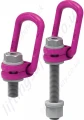
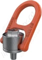
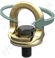
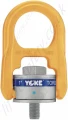
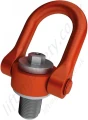
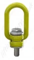
- Gunnebo "DLP" Rotating Lifting Point
The compact design of the De-centered Lifting Point (DLP) makes it ideal in narrow spaces such as corners and edge positions.
The DLP is designed in such a way that the link / lifting eye will fold over the bolt housing, meaning the lifting point takes up minimal space when not in use.
The oblong link will stand up alone which allows for fast and easy rigging, so a hook can almost be single-handedly attached - excellent especially in limited spaces. and because of this, will not rattle and clunk when attached to vibrating machines or vehicles.
Choosing the right lifting point for an operation can be a challenge since most lifting points can be used for several purposes. Safety is of course the highest priority, therefore each DLP sold has been proofloaded 2.5 times the WLL.
DLP Features
- Hexagon makes it easy to install and un-install the DLP lifting point.
- Rotates 360° & pivots 180°.
- Available with a long thread bolt.
- Designed for easy and smooth tilting in any operation.
- The lifting point will always be positioned correctly in the lift thanks to the tilting and rotating functions of the lifting point.
- Sold individually.
- Chains and Hook NOT included.
- Lifting Points with Long Thread are supplied with Nut and Washer.
Typical Applications
- Handling of tools for pressing, moulding and forging.
- 4-point lifting beam for lifting containers.
- Turning/lifting blades for wind turbines.
- Production and handling of turbomachinery.
- Handling of generators.
- Construction.
- Lashing and tie downs.
Dimensions and Specifications: Metric Thread
Standard Length | Long Bolt | Standard Length | |||||||||||||
Part No. | WLL (t)* | B (mm) | C (mm) | D (mm) | E (mm) | F (mm) | G (mm) | L (mm) | L1 (mm) | L (mm) | M (mm) | X (mm) | Y (mm) | Z (mm) | Weight (kg) |
DLP-M8 x 1.25 | 0.35 | 35 | 48 | 10 | 39 | 14 | 10 | 13 | 78 | 98 | 8 | 30 | 55 | 26 | 0.3 |
DLP -M10 x 1.5 | 0.65 | 35 | 48 | 10 | 39 | 14 | 10 | 13 | 78 | 98 | 10 | 30 | 55 | 26 | 0.3 |
DLP -M12 x 1.75 | 1 | 35 | 48 | 12 | 51 | 20 | 14 | 23 | 91 | 78 | 12 | 44 | 59 | 32 | 0.5 |
DLP-M16 x 2 | 1.8 | 35 | 48 | 12 | 51 | 20 | 14 | 23 | 91 | 78 | 16 | 44 | 59 | 32 | 0.5 |
DLP-M20 x 2.5 | 2.6 | 54 | 88 | 18 | 71 | 28 | 18 | 34 | 145 | 84 | 20 | 58 | 90 | 48 | 1.6 |
DLP-M24 x 3 | 4.1 | 54 | 88 | 18 | 71 | 28 | 18 | 34 | 145 | 84 | 24 | 58 | 90 | 48 | 1.7 |
DLP-M30 x 3.5 | 5 | 82 | 94 | 26 | 104 | 39 | 27 | 53 | 182 | 295 | 30 | 88 | 122 | 75 | 5 |
DLP-M36 x 4 | 7 | 82 | 94 | 26 | 104 | 39 | 27 | 53 | 182 | 295 | 36 | 88 | 122 | 75 | 5.2 |
DLP-M42 x 4.5 | 15 | 100 | 103 | 36 | 136 | 54 | 34 | 73 | 216 | 283 | 42 | 113 | 156 | 110 | 11.6 |
DLP-M48 x 5 | 20 | 100 | 103 | 36 | 136 | 54 | 34 | 73 | 216 | 283 | 48 | 113 | 156 | 110 | 11.9 |
*Safety factor 4:1
Dimensions and Specifications: Imperial Thread
Standard Length | Long Bolt | Standard Length | |||||||||||||
Part No. | WLL (t) | B (mm) | C (mm) | D (mm) | E (mm) | F (mm) | G (mm) | L (mm) | L1 (mm) | L (mm) | M (mm) | X (mm) | Y (mm) | Z (mm) | Weight (kg) |
DLP-5/16”-18 UNC | 0.35 | 35 | 48 | 10 | 39 | 14 | 10 | 13 | 78 | 98 | 30 | 55 | 26 | 5/16” | 0.3 |
DLP-3/8”-16 UNC | 0.6 | 35 | 48 | 10 | 39 | 14 | 10 | 13 | 78 | 98 | 30 | 55 | 26 | 3/8” | 0.3 |
DLP-1/2”-13 UNC | 1 | 35 | 48 | 12 | 51 | 20 | 14 | 23 | 91 | 78 | 44 | 59 | 32 | 1/2” | 0.5 |
DLP-5/8”-11 UNC | 1.6 | 35 | 48 | 12 | 51 | 20 | 14 | 23 | 91 | 78 | 44 | 59 | 32 | 5/8” | 0.5 |
DLP-3/4”-10 UNC | 2.2 | 54 | 88 | 18 | 71 | 28 | 18 | 34 | 145 | 84 | 58 | 90 | 48 | 3/4” | 1.6 |
DLP-7/8”-9 UNC | 2.6 | 54 | 88 | 18 | 71 | 28 | 18 | 34 | 145 | 84 | 58 | 90 | 48 | 7/8” | 1.6 |
DLP-1”-8 UNC | 4.1 | 54 | 88 | 18 | 71 | 28 | 18 | 34 | 145 | 84 | 58 | 90 | 48 | 1” | 1.7 |
DLP- 1 1/4”-7 UNC | 5 | 82 | 94 | 26 | 104 | 39 | 27 | 53 | 182 | 295 | 88 | 122 | 75 | 1 1/4” | 5.5 |
DLP-1 1/2”-6 UNC | 7 | 82 | 94 | 26 | 104 | 39 | 27 | 53 | 182 | 295 | 88 | 122 | 75 | 1 1/2” | 5.7 |
DLP-1 3/4”-5 UNC | 15 | 100 | 103 | 36 | 136 | 54 | 34 | 73 | 216 | 283 | 113 | 156 | 110 | 1 3/4” | 11.7 |
DLP-2”- 4.5 UNC | 20 | 100 | 103 | 36 | 136 | 54 | 34 | 73 | 216 | 283 | 113 | 156 | 110 | 2” | 12.1 |
*Safety factor 4:1

DLP (De-centered Lifting Point) Load Chart WLL*
Symmetric Load (t) |
![]() |
![]() |
![]() |
![]() |
||||
No Of Legs. | 1 | 2 | 2 Symmeric | 3 & 4 Symmetric | ||||
Angle ß | 0°< ß < 90° | 0°< ß < 90° | 0-45° | 45-60° | 0-45° | 45-60° | Tightening torque | Spanner size |
DLP -M8 x 1.25 DLP 5/16”-18 UNC |
0.35 0.35 |
0.70 0.70 |
0.5 0.5 |
0.35 0.35 |
0.7 0.7 |
0.5 0.5 |
10 Nm 7 Ft.Lbs |
13 mm 1/2” |
DLP -M10 x 1.5 DLP 3/8”-16 UNC |
0.65 0.60 |
1.30 1.20 |
0.9 0.8 |
0.65 0.60 |
1.4 1.3 |
1.0 1.0 |
15 Nm 11 Ft.Lbs |
13 mm 1/2” |
DLP -M12 x 1.75 DLP 1/2”-13 UNC |
1.0 1.0 |
2.0 2.0 |
1.4 1.4 |
1.0 1.0 |
2.1 2.1 |
1.5 1.5 |
27 Nm 20 Ft.Lbs |
24 mm 15/16” |
DLP -M16 x 2 DLP 5/8”-11 UNC |
1.8 1.6 |
3.6 3.2 |
2.5 2.2 |
1.8 1.6 |
3.7 3.3 |
2.7 2.4 |
60 Nm 44 Ft.Lbs |
24 mm 15/16” |
DLP -M20 x 2.5 DLP -3/4”-10 UNC DLP -7/8”-9 UNC |
2.6 2.2 2.6 |
5.2 4.4 5.2 |
3.5 3.0 3.5 |
2.6 2.2 2.6 |
5.4 4.6 5.4 |
3.9 3.3 3.9 |
90 Nm 66 Ft.Lbs 66 Ft.Lbs |
32 mm 1 5/16” 1 5/16” |
DLP -M24 x 3 DLP -1”-8 UNC |
4.1 4.1 |
8.2 8.2 |
5.7 5.7 |
4.1 4.1 |
8.6 8.6 |
6.1 6.1 |
135 Nm 100 Ft.Lbs |
32 mm 1 5/16” |
DLP -M30 x 3.5 DLP -1 1/4”-7 UNC |
5.0 5.0 |
10.0 10.0 |
7.0 7.0 |
5.0 5.0 |
10.5 10.5 |
7.5 7.5 |
270 Nm 200 Ft.Lbs |
55 mm 2 1/4” |
DLP -M36 x 4 DLP -1 1/2”-6 UNC |
7.0 7.0 |
14.0 14.0 |
9.8 9.8 |
7.0 7.0 |
14.7 14.7 |
10.5 10.5 |
320 Nm 236 Ft.Lbs |
55 mm 2 1/4” |
DLP -M42 x 4.5 DLP -1 3/4”-5 UNC |
15.0 15.0 |
30.0 30.0 |
21.0 21.0 |
15.0 15.0 |
31.5 31.5 |
22.5 22.5 |
600 Nm 440 Ft.Lbs |
75 mm 3” |
DLP -M48 x 5 DLP -2”-4.5 UNC |
20.0 20.0 |
40.0 40.0 |
28.0 28.0 |
20.0 20.0 |
42.0 42.0 |
30.0 30.0 |
800 Nm 590 Ft.Lbs |
75 mm 3” |
*Safety factor 4:1
You May Also Like
Contact Us About This Product
If you wish to receive a quote for this product, please use the tab above, this form is for general enquiries regarding this product only.
You can also Request a Quote using the Quote tab above!
You can easily add more than one item to the Quote Request. This is highly recommended as we will be able to suit your needs much more efficiently.