Load Arrestor Information
Load arrestors are designed as fall protection for materials and serve a similar purpose to a fall arrest inertia reel or self-retracting lifeline that is used for personal fall protection of personnel. The load arrestor, connected to a load, will stop a fall should it occur. The load arrestor will not only protect equipment attached to it, but also people and other items under the suspended equipment.
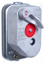
The load arrestor is attached to a structure via the bolt holes, and the equipment that is to be protected is to be attached to the wire rope. The wire rope is kept under tension and is automatically rewound on the wire rope drum. A drum spring will keep the wire rope under tension.
If a fall occurs, a ratchet pawl will engage with a ratchet ring when the wire speed exceeds 0.5 m/sec. The ratchet ring is then screwed into the cover and compresses the brake disc until all energy has been absorbed and the equipment is safely held; thus, the load is arrested, undamaged by the wire rope.
During a load arrest, the brake disc also pushes the indication pin through the cover. The indication pin protruding by a few millimetres indicates that the load arrestor should immediately be removed, serviced, and have the brake reset.

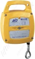
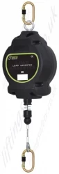
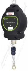
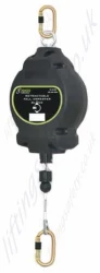
Small Load Arrestor

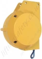
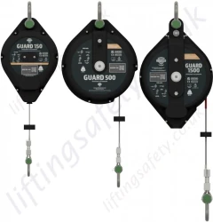
Medium Load Arrestor

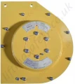
Large Load Arrestors
Load Arrestor Features
- The Load arrestor provides independent protection that will arrest the fall of a load in the event of the primary system failing, and, as it is completely independent of the primary lifting system, it lowers the risk of equipment damage and protects workers in and around the area of the incident.
- This range of load arrestors comes with safe working loads between 300kg and 3000kg, with a variety of wire cable lengths and arrest speeds.
- The load arrestor is installed adjacent to the primary lifting device and fixed to a suitable anchorage point. Its retractable steel cable is then secured to the load. The wire rope is attached to the arrestor using an internal spring-loaded drum that keeps the rope under a constant light tension yet allows unrestricted movement of the protected load.
- If the primary lifting device fails, and the load begins to fall, the arrestor senses a descent speed in excess of the set arrest speed and automatically engages an internal inertia-activated mechanical brake that acts on the rope drum. This arrests the fall over a short distance to reduce the shock forces exerted on the load and the load arrestor.
- Our range of load arrestors is only designed for indoor use.
- All of these standard load arrestor units operate at a speed of 0.5 metres per second, but there is a choice of 0.3 and 1.0 metres per second operation; however, this needs to be stated at the time of order. (Only 0.5 and 1.0 metres per second activation springs are available on the medium and large range)
Servicing the Load Arrestor
Servicing should be carried out at 12 monthly intervals based on a standard working week with up to 60 cycles a day, but should not exceed 7000 cycles before servicing. This should be based on the user's risk assessment, taking into account environmental and working conditions, etc..
Then the servicing periods should be reduced accordingly. If the unit has arrested a fall or if the activation pin (fall indicator) is protruding, it should be withdrawn from service immediately.
Multiple Load Arrestors - To Increase Capacity
Small, Medium and Large
Under special circumstances multiple load arrestors can be used on a single application as confirmed by the manufacturer; tests have been carried out that proved that you can mount up to 4 load arrestors to a single item that requires fall protection (e.g. one for each corner), thus increasing the maximum potential arresting capacity. This works because there is a variance in the stopping distance, so all 4 units would work as designed. As the ratchet pawls will not engage simultaneously in two load arrestors, it is vital that the load arrestors are installed at a sufficient distance apart with unrestricted vertical movement under each unit to enable the falling force to be properly divided between them. Please contact our technical representatives before applying this installation procedure.
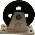
Load Arrestor used with a Pulley Sheave - For Increased Capacity
Small, Medium and Large
Combined with A Pulley
The load arrestor can be combined with a pulley and can if properly installed, can protect twice the nominal load but with half the wire length capacity. The load arrestor must, for this application, be ordered complete with pulley and modified ratchet pawl springs to maintain an engagement speed of 0.5 m/s. The wire rope should move in the same direction on both the wire drum and the external pulley.

Pulley in Cramp Conditions
The Load Arrestor can be used in cramped conditions by using a pulley as shown below. The LoadArrestor must under all circumstances be installed so that the wire drum is working vertically. For this application, the anchorage point for the external pulley must be calculated according to the specification table below.

All units have to have a vertical feed to the unit, although you can put the wire on a pulley so that it will work if an arc is required, but it will keep the feed vertical to the unit. In that case, it would not halve the load or speed as you are only ensuring that the cable runs vertically.
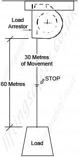
Load Arrestors with Long Cable Lengths
If a customer requires a unit that has 60 metres of cable, though only 30 metres ever needs to be recoiled inside the unit, this can be achieved by putting a clamp on the wire to keep the 30 metres from entering the unit. The only factor is that the recoil spring must be able to cope with the extra weight of the wire. I will do some tests and get you the maximum lengths that can be left outside the housing. (See image to the right)
Main Features
- Independent protection.
- Reduces the risk of equipment damage and protects personnel.
- Three body sizes: small, medium, and large.
- Protect loads from 300kg up to 3000kg.
- Variety of standard cable lengths (other specials available on request).
- Allows unrestricted movement of the protected load.
- Senses a fall speed and automatically engages.
- Arrests falling materials over a short distance.
- Absorbs the shock forces.
Applications
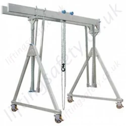
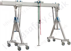
The Load Arrestors can be used in conjunction with a large variety of lifting devices, or protection of overhead loads:
- Cranes
- Hoists
- Lifts
- Lighting rigs
- Tools/equipment
Options Available
| Model |
Body Size |
Capacity |
Minimum Load (kg) |
Cable Length (m) |
Brake Activating Speed (m/s) |
Rope Dia. (mm) |
Rope M.B.S. (kN) |
Max Stopping Distance (mm) |
Minimum Anchorage Capability (kN) |
Maximum cycles per day |
Maximum cycles between servicing |
Approx. Dimensions (mm) |
Weight (kg) |
| SELS-300-12 |
Small |
300kg |
2.5 |
12 (1- fall) |
0.5 std (0.33 or 1 - special) |
5 |
16.0 |
1000 |
15.8kN |
TBA |
TBA |
200 x 260 x 112 |
8.5 |
| SELS-400-8 |
Small |
400kg |
2.5 |
8 (1- fall) |
0.5 std (0.33 or 1 - special) |
6 |
24.0 |
1000 |
22.8kN |
TBA |
TBA |
200 x 260 x 112 |
8.5 |
| SELS-500-5 |
Small |
500kg |
2.5 |
5 (1- fall) |
0.5 std (0.33 or 1 - special) |
7 |
32.0 |
1000 |
31.0kN |
TBA |
TBA |
200 x 260 x 112 |
8.5 |
| SELS-500-20 |
Medium |
500kg |
5 to 7.5 |
20 (1- fall) |
0.5 std (1 -special) |
7 |
32.0 |
600 |
31.0kN |
TBA |
TBA |
368 x 435 x 236 |
41
|
| SELS-600-6P |
Small |
600kg |
2.5 |
6 (2- fall c/w pulley) |
0.5 |
5 |
16.0 |
1000 |
15.8kN x2 (31.6kN) |
TBA |
TBA |
200 x 260 x 112 |
8.5 |
| SELS-800-4P |
Small |
800kg |
2.5 |
4 (2- fall c/w pulley) |
0.5 |
6 |
24.0 |
1000 |
22.8kN x2 (45.6kN) |
TBA |
TBA |
200 x 260 x 112 |
8.5 |
| SELS-800-17 |
Medium |
800kg |
5 to 7.5 |
17 (1- fall) |
0.5 std (1m/s - special) |
8 |
41.0 |
600 |
40.5kN |
TBA |
TBA |
368 x 435 x 236 |
41 |
| SELS-1000-2.5P |
Small |
1000kg |
2.5 |
2.5 (2- fall c/w pulley) |
0.5 |
7 |
32.0 |
1000 |
31.0kN x2 (62.0kN) |
TBA |
TBA |
200 x 260 x 112 |
8.5 |
| SELS-1000-10P |
Medium |
1000kg |
5 to 7.5 |
10 (2- fall c/w pulley) |
0.5 |
7 |
32.0 |
500 |
31.0kN x2 (62.0kN) |
TBA |
TBA |
368 x 435 x 236 |
41 |
| Model |
Body Size |
Capacity |
Minimum Load (kg) |
Cable Length (m) |
Brake Activating Speed (Arrest Speed)(m/s) |
Rope Dia. (mm) |
Rope M.B.S. (kN) |
Max Stopping Distance (mm) |
Minimum Anchorage Capability (kN) |
Maximum cycles per day |
Maximum cycles between servicing |
Approx. Dimensions (mm) |
Weight (kg) |
| SELS-1000-12 |
Medium |
1000kg |
5 to 7.5 |
12 (1- fall) |
0.5 std (1m/s - special) |
9 |
48.0 |
800 |
51.0kN |
TBA |
TBA |
368 x 435 x 236 |
41 |
| SELS-1000-14.3 |
Medium |
1000kg |
5 to 7.5 |
14.3 (1- fall) |
0.5 std (1 - special) |
11 |
71.0 |
500 |
51.0kN |
TBA |
TBA |
368 x 435 x 236 |
41 |
| SELS-1000-30 |
Large |
1000kg |
15 |
30 (1- fall) |
0.5 std (1 - special) |
9 |
48 |
800 |
TBA |
TBA |
TBA |
470 x 535 x 220 |
105 |
| SELS-1300-20 |
Large |
1300kg |
15 |
20 (1- fall) |
0.5 std (1 - special) |
10 |
59 |
800 |
TBA |
TBA |
TBA |
470 x 535 x 220 |
105 |
| SELS-1500-5 |
Medium |
1500kg |
TBA |
5 (1-fall) |
0.5 std (1 - Special) |
11 |
71 |
500 |
TBA |
TBA |
TBA |
368 x 435 x 236 |
41 |
| SELS-1500-15 |
Large |
1500kg |
15 |
15 (1- fall) |
0.5 std (1 - special) |
11 |
71 |
1000 |
TBA |
TBA |
TBA |
470 x 535 x 220 |
105 |
| SELS-1600-8.5P |
Medium |
1600kg |
5 to 7.5 |
8.5 (2- fall c/w pulley) |
0.5 |
8 |
41.0 |
500 |
40.5kN x2 (81.0kN) |
TBA |
TBA |
368 x 435 x 236 |
41 |
| SELS-2000-6P |
Medium |
2000kg |
5 to 7.5 |
6 (2- fall c/w pulley) |
0.5 |
9 |
48.0 |
500 |
51.0kN x2 (102.0kN) |
TBA |
TBA |
368 x 435 x 236 |
41 |
| SELS-2000-7.15P |
Medium |
2000kg |
5 to 7.5 |
7.15 (2-fall c/w pulley) |
0.5 |
11 |
71.0 |
500 |
51.0kN x2(102.0kN) |
TBA |
TBA |
368 x 435 x 236 |
41 |
| SELS-2000-15P |
Large |
2000kg |
15 |
15 (2- fall c/w pulley) |
0.5 |
9 |
48 |
500 |
TBA |
TBA |
TBA |
470 x 535 x 220 |
105 |
| SELS-2600-10P |
Large |
2600kg |
15 |
10 (2- fall c/w pulley) |
0.5 |
10 |
59 |
500 |
TBA |
TBA |
TBA |
470 x 535 x 220 |
105 |
| SELS-3000-2.5P |
Medium |
3000kg |
TBA |
2.5 (2-fall c/w pulley) |
0.5 |
11 |
71 |
500 |
TBA |
TBA |
TBA |
368 x 435 x 236 |
41 |
| SELS-3000-7.5P |
Large |
3000kg |
15 |
7.5 (2- fall c/w pulley) |
0.5 |
11 |
71 |
700 |
TBA |
TBA |
TBA |
470 x 535 x 220 |
105 |