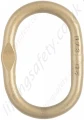
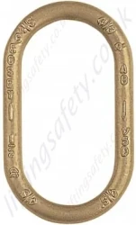
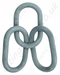
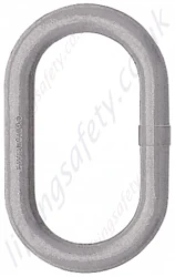
Welded master link / main ring with engineered flat. 1.6 tonne to 65.3 tonne WLL.
Model:
Crosby A-344
Quick Ref:
WMLA-2469
More from:
The ultimate Load is 5 times the Working Load Limit. Applications with wire rope and synthetic sling generally require a design factor of 5. Based on single leg sling (in-line load), or resultant load on multiple legs with an included angle less than or equal to 120 degrees. ** Proof Test Load equals or exceeds the requirement of ASTM A952(8.1) and ASME B30.9. For use with chain slings.
Alloy Steel - Quenched and Tempered.
Individually Proof Tested to values shown, with certification.
Proof Tested with 70% inside width special fixtures sized to prevent localized point loading per EN 1677-4.
Each link has a Product Identification Code (PIC) for material traceability, along with the size and the name Crosby® or “CG”.
Large inside width and length to allow additional room for sling hardware and crane hook.
Engineered Flat for use with S-1325A coupler link.
Meets or exceeds all requirements of ASME B30.26 including identification, ductility, design factor, proof load and temperature requirements. Importantly, these links meet other critical performance requirements including fatigue life, impact properties and material traceability, not addressed by ASME B30.26.
Master links are type approved to DNV Certification Notes 2.7-1- Offshore Containers. These Crosby master links are 100% proof tested and impact tested.The tests are conducted by Crosby and 3.1 test certification is available upon request.
12mm through 32mm have Engineered Flat.
Metric Dimensions & Specifications
Size
A-344 Stock No.
Weight (kg)
Working Load Limit (t)*
Proof Load (kN)**
Dimensions (mm)
Engineered Flat Size for S-1325A (mm)
(mm)
(In.)
A (mm)
B (mm)
C (mm)
G (mm)
12
7/16
1256862
0.30
1.60
39
12.0
60.0
120
6.50
6
13
1/2
1256932
0.36
2.50
61
13.0
60.0
120
6.50
7-8
17
11/16
1257002
0.86
4.10
101
17.0
90.0
160
8.50
10
19
3/4
1257072
1.08
6.70
164
19.0
90.0
160
8.50
10
20
3/4
1257082
1.17
6.70
164
20.0
80.0
150
8.50
–
22
7/8
1257214
1.59
8.50
208
22.0
90.0
170
10.5
–
22
7/8
1257212
1.63
8.50
208
22.0
100
180
10.5
13
22
7/8
1257215
2.39
6.30
154
22.0
145
275
10.5
–
25
1
1257282
2.43
11.5
282
25.0
115
205
13.5
16
25
1
1257302
2.31
11.5
282
25.0
100
190
13.5
–
25
1
1257332
3.35
8.90
218
25.0
145
275
13.5
–
28
1-1/8
1257352
3.22
12.9
316
28.0
110
210
13.5
–
28
1-1/8
1257382
3.91
13.0
319
28.0
145
275
13.5
16
31
1-7/32
1257422
4.86
17.0
417
31.0
145
275
16.7
–
32
1-1/4
1257442
5.30
17.0
417
32.0
140
270
16.7
–
36
1-7/16
1257492
6.87
24.0
588
36.0
155
285
–
–
38
1-1/2
1257502
7.63
31.5
772
38.0
140
270
–
–
40
1-9/16
1257532
8.96
28.1
689
40.0
160
300
–
–
45
1-3/4
1257569
10.31
32.0
785
45.0
140
250
–
–
45
1-3/4
1257564
12.70
38.3
939
45.0
170
320
–
–
45
1-3/4
1257562
12.82
38.3
939
45.0
180
340
–
–
50
1-31/32
1257582
17.60
45.0
1103
50.0
200
380
–
–
51
2
1257632
18.72
45.0
1103
51.0
215
390
–
–
57
2-1/4
1257652
24.5
65.3
1601
57.0
203
406
–
–
*Ultimate Load is 5 times the Working Load Limit. Applications with wire rope and synthetic sling generally require a design factor of 5. **Proof Test Load equals or exceeds the requirement of ASTM A952(8.1) and ASME B30.9.
If you wish to receive a quote for this product, please use the tab, this form is for general enquiries regarding this product only.
Regarding: Crosby A344 Welded Master Link
Did you know?
You can also request a quote through the pricing tab!
You can easily add more than one item to the Quote Request. This is highly recommended as we will be able to suit your needs much more efficiently.
Share this page!
The ultimate Load is 5 times the Working Load Limit. Applications with wire rope and synthetic sling generally require a design factor of 5. Based on single leg sling (in-line load), or resultant load on multiple legs with an included angle less than or equal to 120 degrees. ** Proof Test Load equals or exceeds the requirement of ASTM A952(8.1) and ASME B30.9. For use with chain slings.
Alloy Steel - Quenched and Tempered.
Individually Proof Tested to values shown, with certification.
Proof Tested with 70% inside width special fixtures sized to prevent localized point loading per EN 1677-4.
Each link has a Product Identification Code (PIC) for material traceability, along with the size and the name Crosby® or “CG”.
Large inside width and length to allow additional room for sling hardware and crane hook.
Engineered Flat for use with S-1325A coupler link.
Meets or exceeds all requirements of ASME B30.26 including identification, ductility, design factor, proof load and temperature requirements. Importantly, these links meet other critical performance requirements including fatigue life, impact properties and material traceability, not addressed by ASME B30.26.
Master links are type approved to DNV Certification Notes 2.7-1- Offshore Containers. These Crosby master links are 100% proof tested and impact tested.The tests are conducted by Crosby and 3.1 test certification is available upon request.
12mm through 32mm have Engineered Flat.
Metric Dimensions & Specifications
Size
A-344 Stock No.
Weight (kg)
Working Load Limit (t)*
Proof Load (kN)**
Dimensions (mm)
Engineered Flat Size for S-1325A (mm)
(mm)
(In.)
A (mm)
B (mm)
C (mm)
G (mm)
12
7/16
1256862
0.30
1.60
39
12.0
60.0
120
6.50
6
13
1/2
1256932
0.36
2.50
61
13.0
60.0
120
6.50
7-8
17
11/16
1257002
0.86
4.10
101
17.0
90.0
160
8.50
10
19
3/4
1257072
1.08
6.70
164
19.0
90.0
160
8.50
10
20
3/4
1257082
1.17
6.70
164
20.0
80.0
150
8.50
–
22
7/8
1257214
1.59
8.50
208
22.0
90.0
170
10.5
–
22
7/8
1257212
1.63
8.50
208
22.0
100
180
10.5
13
22
7/8
1257215
2.39
6.30
154
22.0
145
275
10.5
–
25
1
1257282
2.43
11.5
282
25.0
115
205
13.5
16
25
1
1257302
2.31
11.5
282
25.0
100
190
13.5
–
25
1
1257332
3.35
8.90
218
25.0
145
275
13.5
–
28
1-1/8
1257352
3.22
12.9
316
28.0
110
210
13.5
–
28
1-1/8
1257382
3.91
13.0
319
28.0
145
275
13.5
16
31
1-7/32
1257422
4.86
17.0
417
31.0
145
275
16.7
–
32
1-1/4
1257442
5.30
17.0
417
32.0
140
270
16.7
–
36
1-7/16
1257492
6.87
24.0
588
36.0
155
285
–
–
38
1-1/2
1257502
7.63
31.5
772
38.0
140
270
–
–
40
1-9/16
1257532
8.96
28.1
689
40.0
160
300
–
–
45
1-3/4
1257569
10.31
32.0
785
45.0
140
250
–
–
45
1-3/4
1257564
12.70
38.3
939
45.0
170
320
–
–
45
1-3/4
1257562
12.82
38.3
939
45.0
180
340
–
–
50
1-31/32
1257582
17.60
45.0
1103
50.0
200
380
–
–
51
2
1257632
18.72
45.0
1103
51.0
215
390
–
–
57
2-1/4
1257652
24.5
65.3
1601
57.0
203
406
–
–
*Ultimate Load is 5 times the Working Load Limit. Applications with wire rope and synthetic sling generally require a design factor of 5. **Proof Test Load equals or exceeds the requirement of ASTM A952(8.1) and ASME B30.9.