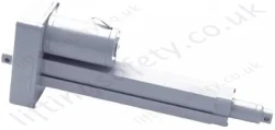
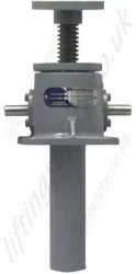
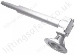
Shopping Basket
Your shopping basket is currently empty
Quote Request Basket
Your quote request basket is currently empty
Continuous Duty Cycle Actuators are specifically designed for continuous operation.
The gear set operates in an oil filled bath for thermal efficiency and long life.
The shell is made of a finned aluminium for better cooling properties.
Additionally the ball screw system increases the efficiency of these models.

| Model Number | A | B | C | D | E | F | G | H | I | J | K | L | M | N | O | P | Q | R | S | T | U | V | W | X | Y |
| UM-7512 | 7 | 2 3/4 | 2.20 | 6 | +.001 1.703 | 1.12 | 8.6 | 4.3 | +.000 -.002 .750 | +.000-.002 .500 | 1/2 R | 2 1/4 | 2 3/4 | 5 1/2 | 4 1/2 | 13/32 | +.1, 5 1/4 | .832 | 1.13 | 4.250 | 3.395 | 3/4 | +.005 2.500 | 1.171 Dia. .4130 Lead | 3.75 |
| UM-7516 | 8 3/4 | 2 7/8 | 2.0 | 7 | +.003-.000 2.589 | 1 13/16 | 11 | 5 1/2 | +.000-.002 1.000 | +.000-.002 1.000 | 7/8 R | 2 7/8 | 3 3/4 | 7 1/2 | 5 3/4 | 11/16 | +.1, 5 3/4 | .895 | 1 | 4.937 | 4.332 | 1 | +.005 2.750 | 1 1/2 Dia. .474 Lead | 4.75 |
| UM-7523 | 13 3/4 | 5 1/8 | 3.75 | 11 | +.005-.000 3.750 | 2.38 | 17 | 7 | +.000-.002 1.750 | +.000-.002 1.000 | 1 3/8 R | 3 3/4 | 5 1/8 | 10 1/4 | 7 1/2 | 13/16 | +.1, 7 3/4 | +0.10 1.582 | 2 1/4 | 5.375 | +.040 6.706 | 1 1/2 | +.005 3.750 | 2 1/4 Dia. .500 Lead | 8.0 |

| Model Number | A | B | C | D | E | F | G | H | I | J | K | L | M | N | O | P | Q | R | S | T | U | V | W | X | Y |
| DM-7512 | 7 | 2 3/4 | 2.20 | 6 | +.001 1.703 | 1.12 | 8.6 | 4.3 | +.000 -.002 .750 | +.000-.002 .500 | 1/2 R | 2 1/4 | 2 3/4 | 5 1/2 | 4 1/2 | 13/32 | +.1, 5 1/4 | .832 | 1.13 | 4.250 | 3.395 | 3/4 | +.005 2.500 | 1.171 Dia. .4130 Lead | 3.75 |
| DM-7516 | 8 3/4 | 2 7/8 | 2.0 | 7 | +.003-.000 2.589 | 1.81 |
11 | 5 1/2 | +.000-.002 1.000 | +.000-.002 1.000 | 7/8 R | 2 7/8 | 3 3/4 | 7 1/2 | 5 3/4 | 11/16 | +.1, 5 3/4 | .895 | 1 | 4.937 | 4.332 | 1 | +.005 2.750 | 1 1/2 Dia. .474 Lead | 4.75 |
| DM-7523 | 13 3/4 | 5 1/8 | 3.75 | 11 | +.005-.000 3.750 | 2.38 | 14 | 7 | +.000-.002 1.750 | +.000-.002 1.000 | 1 3/8 R | 3 3/4 | 5 1/8 | 10 1/4 | 7 1/2 | 13/16 | +.1, 7 3/4 | +0.10 1.582 | 2 1/4 | 5.375 | +.040 6.706 | 1 1/2 | +.005 3.750 | 2 1/4 Dia. .500 Lead | 8.0 |

| Model Number | Dimensions | |||||||||||||||||||||||||
| A | B | C | D | E | F | G | H | I | J | K | L | M | N | O | P | Q* | R | S | T | U** | V | W | X | Y | Z | |
| 7511 | 7 | 2 3/4 | 2.20 | 6 | +.001 - .703 | 1.12 | 8.6 | 4.3 | 3/4-16UNF-2A | +.000-.002.500 | 1/2 R | 2 1/4 | 2 3/4 | 5 1/2 | 4 1/2 | 13/32 | +.06 8.4 | +.06 8.4 | 1 1/8 | 1 21/32 | 7 O.D. X 4 I.D. | 3/4 | +.005 2.500 | 1.171 Dia. .4130 Lead | 2 | 1.5 |
| 7515 | 8 3/4 | 2 7/8 | 2 | 7 | + .003 - .000 2.598 | 1.68 | 11 | 5.5 | 1-14UNS-2A | +.000-.002 1.000 | 7/8 R | 2 7/8 | 3 3/4 | 7 1/2 | 5 3/4 | 11/16 | +1 11.2 | +.1 9.2 | 1 1/8 | 2 3/8 | 7 O.D. X 4 3/4 I.D. | 1 | +.005 2.750 | 1 1/2 Dia. .474 Lead | 2 | - |
| 7522 | 13 3/4 | 5 1/8 | 3 3/4 | 11 | +.005 - .000 3.750 | 2.38 | 14 | 7.0 | 1 3/4-12UN-2A | +.000-.002 1.000 | 2 3/8 R | 3 3/4 | 5 1/8 | 10 1/4 | 7 1/2 | 13/16 | +1 16.6 | +.1 13.2 | 2 1/4 | 3 1/2 | 9.8 O.D. X 6.8 I.D. | 1 1/2 | +.005 3.750 | 2 1/4 Dia. .500 Lead | 3 | - |
* Hold back torque is restraining torque at the worm shaft, to keep the load from running down.
| Model Number | 7512 | 7516 | 7523 |
| Max Load Capacity (lbs) | 3500 | 12000 | 27000 |
| Rated Load Capacity (lbs) | 2000 | 5200 | 13000 |
| Diameter of Lifting Screw (inch) | 1.171 .413 Lead | 1.5 .473 Lead | 2.250 .50 Lead |
| Base Sizes (inch) | 5 1/2 x 7.0 | 7 1/2 x 8 3/4 | 10 1/4 x 13 3/4 |
| Worm Gear Ratio | 6:1 | 8:1 | 10 2/3:1 |
| Turns of Worm for 1" Raise | 14.5 | 16.888 | 21.333 |
| Horsepower per Jack (maximum) @ 1750 R.P.M | 2 | 5 | 10 |
| Starting Torque Max. Load (in-lbs) | 75 | 200 | 420 |
| Running Torque Max. Load (in-lbs) | 60 | 170 | 350 |
| Jack Efficiency Rating (%) | 70 | 70 | 65 |
| Weight with Base Raise of 6" (lbs) | 18 | 42 | 93 |
| Weight for each Additional 1" Raise (lbs) | .42 | .85 | 1.50 |
| Hold Back Torque* at Rated Load (lb-ft) | 7 | 9 | 12 |
* Hold back torque is restraining torque at the worm shaft, to keep load from running down.
| Model Number | 7511 | 7515 | 7522 |
| Max Load Capacity (lbs) | 3500 | 12000 | 27000 |
| Rated Load Capacity (lbs) | 2000 | 5200 | 13000 |
| Diameter of Lifting Screw (inch) | 1.171 .413 Lead | 1.5 .473 Lead | 2.250 .50 Lead |
| Closed Height (inch) | 10 1/4 | 12 1/4 | 16 1/2 |
| Base Size (inch) | 5 1/2 7.0 | 7 1/2 8 3/4 | 10 1/4 13 3/4 |
| Worm Gear Ratio | 6:1 | 8:1 | 10 2/3:1 |
| Turns of Worm for 1" Raise | 14.5 | 16.888 | 21.333 |
| Horsepower per Jack (maximum) @ 1750 rpm | 2 | 5 | 10 |
| Starting Torque Max. Load (in-lbs) | 75 | 200 | 420 |
| Running Torque Max. Load (in-lbs) | 60 | 170 | 350 |
| Jack Efficiency Rating (%) | 70 | 70 | 65 |
| Hold Back Torque* at Rated Load (lb-ft) | 7 | 9 | 12 |
| Weight with Base Raise of 6" (lbs) | 19 | 43 | 95 |
| Weight for each Additional 1" Raise (lbs) | .42 | .85 | 1.50 |

| Index Number | Part Name | Quantity |
| 1 | Screw, Set (shell cap) | 2 |
| 2 | Shell Cap | 1 |
| 3 | Shell, Actuator | 1 |
| 4 | Bearing, Top & Bottom | 2 |
| 5 | Ball Screw | 1 |
| 6 | Screws, Set (locknut) (7522 model) | 1 |
| 7 | Worm gear | 1 |
| 8 | Gear Extension | 1 |
| 9 | Oil Seal (gear) | 2 |
| 10 | "O" Ring | 1 |
| 11* | Thrustwasher | 1 |
| 12* | Thrustwasher | 1 |
| 13 | Key | 1 |
| 14 | Nut, Lock | 1 |
| 15 | Screw, Cap | 8 |
| 16 | Flange, Worm | 2 |
| 17 | Shim, Flange | 2 |
| 18 | Seal, Oil (worm) | 2 |
| 19 | Worm | 1 |
| 20 | Bearing, Worm | 2 |
| 21 | Oil Plug | 3 |
| 22 | Name Plate | 1 |
| 23 | Plug (7523 Model Inverted) | 1 |
| 24 | Ball Nut & Flange Adaptor Assy. (consists of index numbers, 24A thru 30.) | 1 |
| 24A** | Ball Nut (body) | 1 |
| 25** | Deflector, Yoke | As Required |
| 26A** | Guide, Ball (used when yoke deflectors are used) | As Required |
| 26B** | Guide, Ball (used when yoke deflectors are not used) | As Required |
| 27** | Clamp, Ball Guide | As Required |
| 28** | Nut, Clamp Fastener | As Required |
| 29*** | Bearing Balls (only in sets) specify if oversized balls are required) | |
| 30** | Flange Adaptor | |
| 31 | Guide Bushing (inverted models only) Screw Drive (name plate) | 2 |

| Index Number | Part Name | Quantity |
| 1 | Screw, Set |
2 |
| 2 | Cap, Shell |
1 |
| 3 | Shell |
1 |
| 4 | Bearing, Load |
2 |
| 5 | Pipe, Bottom |
1 |
| 6 | Ball Screw |
1 |
| 7 | Ball Nut Assembly (Consists of Index Numbers 24 thru 29) |
1 |
| 8 | Bearing Retainer |
1 |
| 9 | Screw, Set |
3 |
| 10 | Worm Gear |
1 |
| 11 | Screw, Cap |
1 |
| 12 | Washer, Lock |
1 |
| 13 | Disc, Retaining |
1 |
| 14 | Screw, Hex Head Cap and Washer |
8 |
| 16 | Flange | 2 |
| 17 | Shim, Flange |
2 |
| 18 | Seal, Oil |
2 |
| 19 | Worm | 1 |
| 20 | Bearing, Worm |
2 |
| 21 | Bushing, Guide (inverted models only) |
1 |
| 22 | Oil Plug |
2 |
| 23 | Name Plate |
1 |
| 24* | Ball Nut (body) |
1 |
| 25* | Deflector, Yoke |
As Required |
| 26A* | Guide, Ball (used when yoke deflectors are used) |
As Required |
| 26B* | Guide, Ball (used when yoke deflectors aren't used) | As Required |
| 27* | Clamp, Ball Guide |
As Required |
| 28* | Nut, Clamp Fastener |
As Required |
| 29** | Bearing Balls, (replace only in set) (specify if oversized balls are required) |
1 |
| 30 | Sealing Cylinder |
1 |
| 31 | Oil Seal | 2 |
| 32 | "O" Ring |
1 |
| 33 | Screw, Set |
3 |
If you wish to receive a quote for this product, please use the tab, this form is for general enquiries regarding this product only.
You can also request a quote through the pricing tab!
You can easily add more than one item to the Quote Request. This is highly recommended as we will be able to suit your needs much more efficiently.
LiftingSafety uses cookies to improve your user experience.
Find out more