
- Lifting Equipment
-
Height Safety
Height Safety Equipment
- Material Handling & Jacking Equipment
- Shop by Brand
- Clearance
-
Contact
Get In Touch
- Home/
- Lifting Equipment/
- General Industrial Lifting Equipment/
- Chain Sling Components/
- Master Links and Quad Assemblies/
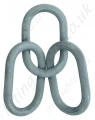
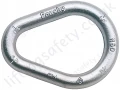
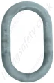
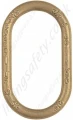
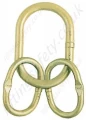
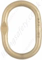
- Crosby A344 Welded Master Link
The ultimate Load is 5 times the Working Load Limit. Applications with wire rope and synthetic sling generally require a design factor of 5. Based on single leg sling (in-line load), or resultant load on multiple legs with an included angle less than or equal to 120 degrees. ** Proof Test Load equals or exceeds the requirement of ASTM A952(8.1) and ASME B30.9. For use with chain slings.
- Alloy Steel - Quenched and Tempered.
- Individually Proof Tested to values shown, with certification.
- Proof Tested with 70% inside width special fixtures sized to prevent localized point loading per EN 1677-4.
- Each link has a Product Identification Code (PIC) for material traceability, along with the size and the name Crosby® or “CG”.
- Large inside width and length to allow additional room for sling hardware and crane hook.
- Engineered Flat for use with S-1325A coupler link.
- Meets or exceeds all requirements of ASME B30.26 including identification, ductility, design factor, proof load and temperature requirements. Importantly, these links meet other critical performance requirements including fatigue life, impact properties and material traceability, not addressed by ASME B30.26.
- Master links are type approved to DNV Certification Notes 2.7-1- Offshore Containers. These Crosby master links are 100% proof tested and impact tested.The tests are conducted by Crosby and 3.1 test certification is available upon request.
- 12mm through 32mm have Engineered Flat.
Metric Dimensions & Specifications
Size | A-344 Stock No. | Weight (kg) | Working Load Limit (t)* | Proof Load (kN)** | Dimensions (mm) | Engineered Flat Size for S-1325A (mm) | ||||
(mm) | (In.) | A (mm) | B (mm) | C (mm) | G (mm) | |||||
12 | 7/16 | 1256862 | 0.30 | 1.60 | 39 | 12.0 | 60.0 | 120 | 6.50 | 6 |
13 | 1/2 | 1256932 | 0.36 | 2.50 | 61 | 13.0 | 60.0 | 120 | 6.50 | 7-8 |
17 | 11/16 | 1257002 | 0.86 | 4.10 | 101 | 17.0 | 90.0 | 160 | 8.50 | 10 |
19 | 3/4 | 1257072 | 1.08 | 6.70 | 164 | 19.0 | 90.0 | 160 | 8.50 | 10 |
20 | 3/4 | 1257082 | 1.17 | 6.70 | 164 | 20.0 | 80.0 | 150 | 8.50 | – |
22 | 7/8 | 1257214 | 1.59 | 8.50 | 208 | 22.0 | 90.0 | 170 | 10.5 | – |
22 | 7/8 | 1257212 | 1.63 | 8.50 | 208 | 22.0 | 100 | 180 | 10.5 | 13 |
22 | 7/8 | 1257215 | 2.39 | 6.30 | 154 | 22.0 | 145 | 275 | 10.5 | – |
25 | 1 | 1257282 | 2.43 | 11.5 | 282 | 25.0 | 115 | 205 | 13.5 | 16 |
25 | 1 | 1257302 | 2.31 | 11.5 | 282 | 25.0 | 100 | 190 | 13.5 | – |
25 | 1 | 1257332 | 3.35 | 8.90 | 218 | 25.0 | 145 | 275 | 13.5 | – |
28 | 1-1/8 | 1257352 | 3.22 | 12.9 | 316 | 28.0 | 110 | 210 | 13.5 | – |
28 | 1-1/8 | 1257382 | 3.91 | 13.0 | 319 | 28.0 | 145 | 275 | 13.5 | 16 |
31 | 1-7/32 | 1257422 | 4.86 | 17.0 | 417 | 31.0 | 145 | 275 | 16.7 | – |
32 | 1-1/4 | 1257442 | 5.30 | 17.0 | 417 | 32.0 | 140 | 270 | 16.7 | – |
36 | 1-7/16 | 1257492 | 6.87 | 24.0 | 588 | 36.0 | 155 | 285 | – | – |
38 | 1-1/2 | 1257502 | 7.63 | 31.5 | 772 | 38.0 | 140 | 270 | – | – |
40 | 1-9/16 | 1257532 | 8.96 | 28.1 | 689 | 40.0 | 160 | 300 | – | – |
45 | 1-3/4 | 1257569 | 10.31 | 32.0 | 785 | 45.0 | 140 | 250 | – | – |
45 | 1-3/4 | 1257564 | 12.70 | 38.3 | 939 | 45.0 | 170 | 320 | – | – |
45 | 1-3/4 | 1257562 | 12.82 | 38.3 | 939 | 45.0 | 180 | 340 | – | – |
50 | 1-31/32 | 1257582 | 17.60 | 45.0 | 1103 | 50.0 | 200 | 380 | – | – |
51 | 2 | 1257632 | 18.72 | 45.0 | 1103 | 51.0 | 215 | 390 | – | – |
57 | 2-1/4 | 1257652 | 24.5 | 65.3 | 1601 | 57.0 | 203 | 406 | – | – |

You May Also Like
Contact Us About This Product
If you wish to receive a quote for this product, please use the tab above, this form is for general enquiries regarding this product only.
You can also Request a Quote using the Quote tab above!
You can easily add more than one item to the Quote Request. This is highly recommended as we will be able to suit your needs much more efficiently.