LIFTING
SAFETY
sales@liftingsafety.co.uk
+44 (0)1977 684 600
- Lifting Equipment
-
Height Safety

Height Safety Equipment
- Material Handling & Jacking Equipment
- Shop by Brand
- Clearance
-
Contact
Get In Touchsales@liftingsafety.co.uk +44 (0)1977 684 600

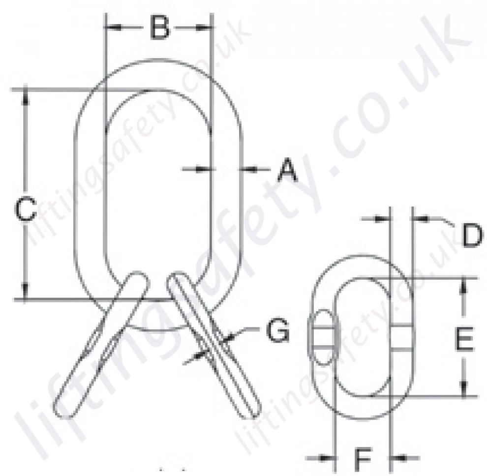
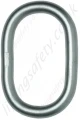
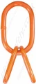
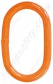
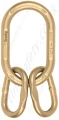
Crosby A345 Forged Alloy Link Assembly, WLL Range from 5.6 tonnes to 169 tonnes
Forged Alloy Master Link Assembly. WLL Range from 5600kg to 169,000kg
Model:
Crosby A-345 / FALA-2696
More from: