Track Clamp Locking Pins
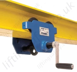
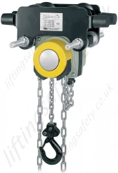
Track Clamp Chain DriveYale locking / braked beam trolleys are available in capacities up to 20 tonne SWL, to suit our customers beam widths. The brake is manually applied to prevent any movement of the trolley.
Yale HTP and HTG Beam Trolleys with Track Clamp
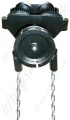
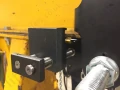
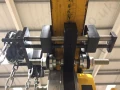
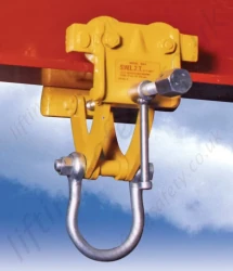
The locking beam trolley incorporates a threaded locking pin connected to a chain wheel. A loop of hand 'pull chain' wraps over the chain wheel (see photo) and down to the operator below. Pulling the hand chain turns the threaded locking pin. Pull the chain clockwise to lock the pin against the steel beam (put the brake on), turning anticlockwise releases the pin (takes off the brake).
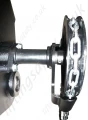
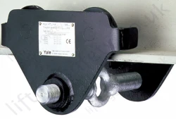
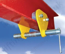
When the trolley is fitted to the beam the user adjusts the 'Take-up screws' (see photo) to approx 1mm from the underside of the lifting beam. When the locking pin is tightened the 'Take-up' pins will be forced to clamp against the underside of beam, resulting in a three point clamp!
A beam trolley enables the exact positioning or easy traversing of large loads with either manual or powered hoisting equipment. It has excellent controlling features due to machined steel wheels mounted on prelubricated, encapsulated ball bearings.
Standard Flange Width and Wide Beam Flange Range.
- Push Travel Trolley (HTP-C) - Capacities 500kg- 5000kg
- Geared Travel Trolley (HTG-C) - Capacities 500kg - 20000kg
- 2.5 metre hand chain drop as standard to suit 3 metre HOL (height of lift).
The HTP-C/HTG-C beam runners are adjustable to fit a wide range of beam widths and profiles (e.g. INP, IPE and IPB). The trolley wheels are designed for a max. beam profile incline of 14%. Adjustments are made by rotating the clevis load bar which also ensure the centred positioning of the hoist in the clevis - no creeping to the left or the right. Anti-tilt and wheel fracture support devices according to DIN 15018 and the machinery directive are standard.
Optional
- Buffers can be fitted.
- Rust and acid resistant hand chains.
- Corrosion resistant trolley.
- Lock nuts for 500kg to 2000kg models.
Technical Data
Capacity
(kg) |
Size |
Beam Flange Width
(mm) |
Max. Flange Thickness
(mm)
|
Min. Radius Curve
(m) |
Effort at WLL
(daN) |
Net weight (kg) |
HTP-C (push trolley)
|
HTG-C (geared trolley) |
| 500 |
A
B |
50-220
160-300 |
25
40 |
0.90 |
3 |
14.5
17.1 |
16.2
19.1 |
| 1000 |
A
B |
50-220
160-300 |
25
40 |
0.90 |
6 |
17.0
20.0 |
19.2
22.1 |
| 2000 |
A
B |
66-220
160-300 |
25
40 |
1.15 |
7 |
24.0
27.3 |
26.0
29.3 |
| 3000 |
A
B |
74-220
160-300 |
25
40 |
1.40 |
7 |
41.2
45.0 |
44.6
48.4 |
| 5000 |
A
B |
90-220
180-300 |
25
40 |
1.80
|
9 |
58.5
62.7 |
62.3
66.5 |
|
Manual (geared) Travel Chain Drive

|
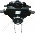
Track Clamp Chain Drive on Geared Trolley
 |
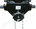
Track Clamp Chain Drive on Push Trolley

|