User Instructions
1. Reference should be made to German Standards accord. BGR 500 or other country specific statutory regulations and inspections are to be carried out by competent persons only.
2. Before installing and every use, visually inspect RUD lifting points, paying particular attention to any evidence of corrosion, wear and weld cracks and deformations. Please ensure compatibility of bolt thread and tapped hole.
3. The material construction to which the lifting point will be attached should be of adequate strength to withstand forces during lifting without deformation. The German testing authority BG, recommends the following minimum for bolt lengths:
1 x M in steel (minimum quality S235JR [1.0037])
1,25 x M in cast iron (for example GG 25)
2 x M in aluminium alloys
2,5 x M in aluminium-magnesium alloys
( M = diameter of RUD lifting point bolt, for ex. M 20 )
When lifting light metals, nonferrous heavy metals and gray cast iron the thread has to be chosen in such a way that the working load limit of the thread corresponds to the requirements of the respective base material.
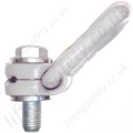
RUD lifting points are delivered with a 100 % crack tested bolt (length up to lmax please see chart 2). When using your own bolts, the bolts have to be 100% crack tested. The min quality of the hexagon bolt had to be 10.9 accord. EN 24014 (DIN 931) with the nominal diameter. For replacement the bolt can be easily hammered out (M8 - M30). The type VLBG 7t M36 is only delivered with a special bolt, therefore it is not possible to use a EN/DIN-bolt.
RUD supplies the Vario length complete with a washer and crack-detected nut corresponding to DIN 980.
4. The lifting points must be positioned on the load in such a way that movement is avoided during lifting.
a.) For single leg lifts, the lifting point should be vertically above the centre of gravity of the load.
b.) For two leg lifts, the lifting points must be equidistant to/or above the centre of gravity of the load.
c.) For three and four leg lifts, the lifting points should be arranged symmetrically around the centre of gravity in the same plane if possible.
5. Load Symmetry:
The working load limit of individual RUD lifting points are calculated using the following formula and are based on symmetrical loading:
|
WLL =
|
G
n x cos ß |
WLL = Working Load Limit
G = Load Weight (kg)
n = Number of load bearing legs
ß = Angle of inclination of the chain to the vertical |
The calculation of load bearing legs is as follows:
| No. Legs |
Symmectrical |
Asymmetrical |
| Two Leg |
2 |
1 |
| Three / Four Leg |
3 |
2 |
(See Table 1 and 2)
6. A Plane bolting surface (ØDB) must be guaranteed. The holes must be drilled with a sufficient depth in order to guarantee compatibility with the supporting surface.
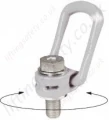
7. The LBG has to be adjustable through 360° when fitted.
For single use just tighten with spanner. For long term application the VLBG should be tightened with torque according to table 2 (+/- 10%).
In case of turning movements (continuous operation) the recommended torques have to be checked regularly (For turning movements we recommend to use the RUD lifting point PowerPoint, WBG-V or WBG).
Adjust to the direction of pull, before attaching to the lifting means. The load ring should be free moving and should not be touching edges.
8. All fittings connected to the VLBG should be free moving. When connecting and disconnecting the lifting means (sling chain) pinches and impacts should be avoided. Damage of the lifting means caused by sharp edges should be avoided as well.
9. To prevent unintended dismounting through shock loading, rotation or vibration thread locking fluid such as Loctite (depending on the application, please pay attention to the manufacturer's instruction) could be used to secure the bolt, or use form-closed devices.
10. Effects of temperature:
Due to the DIN/EN bolts that are used with the VLBG the working load limit should be reduced accordingly:
-40° to 100°C = no reduction (-40°F to 212°F)
100° to 200°C = minus 15% (212°F to 392°F)
200° to 250°C = minus 20% (392°F to 482°F)
250° to 350°C = minus 25% (482°F to 662°F)
Temperatures above 350°C (662°F) are not permitted.
11. RUD-Lifting points must not be used under chemical influences such as acids, alkaline solutions and vapours e.g. in pickling baths or hot dip galvanising plants. If this cannot avoided, please contact the manufacturer indicating the concentration, period of penetration and temperature of use.
12. The places where the lifting points are fixed should be marked with colour.
13. After fitting, an annual inspection or sooner if conditions dicate should be undertaken by a competent person examining the continued suitability. Also after damage and special occurrences.
Inspection criteria concerning paragraphs 2 and 13:
- Ensure correct bolt and nut size, quality and length.
- Ensure compatibility of bolt thread and tapped hole - control of the torque.
- The lifting point should be complete.
- The working load limit and manufacturers stamp should be clearly visible.
- Deformation of the component parts such as body, load ring and bolt.
- Mechanical damage, such as notches, particularly in high stress areas.
- Wear should be no more than 10% of cross sectional diameter.
- Evidence of corrosion.
- Evidence of cracks.
- Damage to the bolt, nut and/or thread.
- The body of the VLBG must be free to rotate.
A non-adherence to this advice may result damages of persons and materials!