-
Lifting Equipment
 Browse Lifting Equipment Shop
- Chain Hoists
-
Wire Rope Hoists
- Hand Operated Wire Rope Winches and Hoists
- Cable Pullers / Hoists, Wire Rope Manual Operation
- Electric Winches and Hoists, AC (Mains Powered)
- Scaffold Hoists & Accessories
- Overhead Wire Rope Crane Hoists
- Hydraulic Wire Rope Winches & Hoists
- Pneumatic Wire Rope Air Winches / Hoists (Lifting and Pulling)
- Vehicle Mounted Winches
- Tractel Wire Rope & Accessories
-
General Lifting Equipment
- Fibre Slings
- Chain Slings Assemblies & Components
- Lifting and Lashing Chain
- Wire Rope Slings & Assemblies
- Shackles
- Eyebolts and Eyenuts
- Lifting & Pulling Clamps
- Lifting Beams & Spreader Beams
- Precast Concrete Lifting
- Lifting Magnets, Permanent, Battery Electric and Manual
- Runway Beam Monorail Crane Trolleys, Push, Geared & Electric
- Equipment Identification Tags
-
Rigging Equipment
- Crosby Lifting & Rigging
- Master Ring & Load Suspension Eyes
- Lifting & Rigging Hooks
- Turnbuckles & Rigging Screws
- Wire Rope Accessories and Fittings
- Snatch Blocks, Sheave Blocks and Crane Pulley Blocks
- Load Restraint Equipment
- General Rigging Accessories
- Lifting & Rigging Swivels - Eye, Hook & Shackle
- Pulley Sheaves
-
Cranes & Gantry Systems
- Portable Davit Arms and Jib Cranes
- Swing Jib Cranes - Installed Floor & Wall Cranes
- Portable/Mobile Free-standing Swing Jib Cranes
- Aluminium Gantries
- Steel Gantries
- Fixed Steel Gantry Systems
- Shearlegs, Tripods & Quadpods
- Overhead Crane Systems
- Portable Shop-Floor/Workshop/Garage Cranes
- Counterbalance Floor, Workshop Cranes
- Scaffolding Runway Beam Systems
-
Material Handling & Jacking Equipment
- Machinery & Load Moving Skates
- Hydraulic Cylinders & Pumps
- Lifting Jacks
- Manhole Cover Lifters
- Hydraulic Pull Cylinders
- Hand Operated Pallet Trucks, Pump Trucks
- Stacker Trucks, Materials Lifts, Manual and Electric
- Genie and Counterbalance Materials Lifters
- Scissor Lift Tables
- Drum Handling Equipment
- Crane Forks
- Load Weighing Equipment - Load Cells
- Tool Spring Balancers / Load Balancers
- Platform Trucks & Trolleys
-
Fork Lift Truck Attachments
- Fork Mounted Man Riding Baskets
- Environment & Waste Handling Attachments
- Fork Lift Truck Mounted Drum Handling Attachments
- Fork Mounted Jib and Hook Attachments
- Fork Truck Booms & Tines
- Stainless Steel Forklift Attachments
- Forklift Truck Fork Extensions
- Multi Fork Attachments
- Fork Truck Scoop Attachments
- Big Bag Fork Truck Attachment
- Closed Base Coil Support Attachments
- Forklift Fork Protection Sleeves
- Snow Plough Fork Lift Truck Attachments
- Other Forklift Truck & Telehandler Attachments
- Specialist Lifting Equipment
- Access and Safety Related
- Workshop and Shop Floor
- Screwjacks & Actuators
-
Height Safety
 Browse Height Safety Store
-
Fall Arrest and Height Safety Harnesses
- General Use Harnesses EN361
- Work Positioning Harnesses EN361 & EN358
- Rope Access Harnesses
- Rescue Harnesses EN1497 & EN361
- Ladies & Childrens Harnesses
- Hi Vis Jacket/Vest Harnesses
- Welders Harnesses
- ATEX (Anti-Static) Harnesses
- Linesman Harnesses
- Oil Derrick Harnesses
- Sport Climbing Harnesses
- Tree Surgeon Positioning Harnesses
- Sit and Chest Harnesses. EN361 EN356 & EN831
- Work Positioning & Restraint Belts EN358
- Fall Arrest, Restraint and Positioning Lanyards
- Height Safety and Fall Arrest Kits
- Inertia Reels and Retrieval Blocks
- Man-riding Hoists & Rescue Winches
-
Fall Arrest & Man-riding Systems
- Fall Arrest Davit Arms & Posts for Working at Height
- Sala Advanced Davit Arm Systems and Components
- Xtirpa Confined Space Davit Arm Systems and Components
- Abtech Man-riding, Fall Arrest and Rescue Davits and Components
- Man-riding & Rescue Tripods & Quadpods
- Manriding Systems, Baskets and Chairs
- Mobile Fall Arrest Gantries, Systems & Steps
- Rope Guided Fall Arresters (Steel & Synthetic Rope)
- Temporary Horizontal Fall Arrest Lifelines
- Vertical Fall Arrest Systems Permanently Installed
- Horizontal Fall Arrest Systems Permanently Installed
- Manriding Baskets Fork Truck and Overhead Crane
- Tank Side Entry and Vehicle Fall Arrest Systems
- Suspension Seats / Bosuns Chair Working at Height
- Collective Fall Arrest Systems
- Man-Riding Sheave Blocks
- Anchorage Devices
- Karabiners & Connectors
- Rescue, Evacuation & Rope Access
-
General Height Safety Gear
- Height Safety Accessories
- Industrial & Climbing Height Safety Helmets
- Synthetic Height Safety Rope & Anchorage Lines
- Height safety Pulley Wheels For Synthetic & Steel Wire Rope
- Black Height Safety Equipment & PPE
- Hot Work Equipment. Cutting, Grinding & Welding
- Cases, Bags, Backpacks, Holdalls. Height Safety Gear
- Telescopic Extension Pole for Height Safety Applications
- Wind Energy Height Safety Equipment
-
Stainless Steel Fall Arrest Equipment
-
Fall Arrest and Height Safety Harnesses
- Home
- About Us
-
Contact
Get In Touch
- Home/
- Lifting Equipment/
- General Industrial Lifting Equipment/
- Lifting Eyebolts & Eye Nuts, Lifting and Lashing Points/
- Weld-on Lifting Eyes and Welded Down Lashing Points/
- Weld-on “Swivel” Lifting Eyes and Welded Down Lashing Points/
- RUD Weld-on “Swivel” and "Pivot" Lifting Eyes and Weld Down Lashing Points/
- RUD "VRBK" Weld Down Corner Load Ring Lifting & Lashing Eye - Range from 4000kg to 50000kg
RUD "VRBK" Weld Down Corner Load Ring Lifting & Lashing Eye - Range from 4000kg to 50000kg
Corner Lifting Eyes for Welding, RUD VRBK.
RUD VRBK-XX / WDLR-50
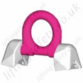
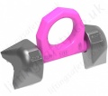
This page has now expired please view the new RUD "VRBK-FIX" Weld on Corner Swivel Load Ring Lifting & Lashing Eye.
The welding point for all 90° edges.
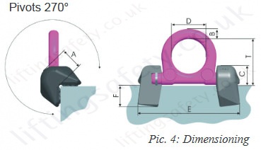
The lifting eye, ready for welding VRBK / RBK is prepared for the direct welding at 90° corners at the transport goods. Directly attached at the corner, it saves the double number of lifting eyes. The welding blocks (made of easy weldable material 1.0577+N St. 52-3) have been provided with distance nabs as gap indication for the weld and stamped with the WLL identification number. The ring latch can be tilted by 270°, made of high-tensile material, 100% crack detected and thus overall loadable.
Eye Plate for Corners
- An enhancement of the well-established RBK - series with an over 30% increment of the WLL.
- A forged ring bracket according to EN1677-1, electromagnetically crack detected, pink powder coated and it can be loaded in all directions.
- Even force distribution owing to the two point attachment.
- Low profile sice it can be folded with in an angle range of 270°.
- The welding block for edges is forged out of a good welding material 1.0577+N (St 52-3) and clearly stamped with an identification number for the permissible WLL.
- Welding should only be carried out by qualified persons according to EN 287-1.
Proof Testing
There is no requirement to Proof Test RUD Products, either Bolt or Weldable after Installation if the user instructions for welding are carried out correctly. The welding should be carried out by a suitably qualified and competent welder/person.
The supporting structure, or the load, should be of adequate strength to take the stresses involved and this is the responsibility of the engineering designer or equivalent.
RUD Lifting and Lashing Products are Manufactured and conform to EN 1677. No further Proof Testing in the field is required. In fact it would be considered that the Product had been overloaded if a Load more than the recommended Working Load Limit had been applied.
RUD products should be regularly inspected in line with the requirements of LOLER and as per our user instructions at intervals decided by a competent person.
Table 1, Load Capacities - Metric
| Method of lift |  |
 |
 |
 |
 |
 |
 |
 |
|||
| Number of legs | 1 | 1 | 2 | 2 | 2 | 2 | 2 | 3 and 4 | 3 and 4 | 3 and 4 | |
| Angle of inclination < ß | 0° | 90° | 0° | 90° | 0-45° | 45-60° | unsymmetrical | 0-45° | 45-60° | unsymmetrical | |
| Factor | 1 | 1 | 2 | 2 | 1.4 | 1 | 1 | 2.1 | 1.5 | 1 | |
| Metric Type | WLL in Metric tonnes (total weight) |
||||||||||
| VRBK-FIX 4t | 4t | 4t | 8t | 8t | 5,6t | 4t | 4t | 8,4t | 6t | 4t | |
| VRBK-FIX 6.7t | 6,7t | 6,7t | 13,4t | 13,4t | 9,4t | 6,7t | 6,7t | 14t | 10t | 6,7t | |
| VRBK-FIX 10t | 10t | 10t | 20t | 20t | 14t | 10t | 10t | 21t | 15t | 10t | |
| VRBK-FIX 31.5t | 31.5t | 31.5t | 63t | 63t | 45t | 31.5t | 31.5t | 66.2t | 47.5t | 31.5t | |
| VRBK 50t | 50t | 50t | 100t | 100t | 70t | 50t | 50t | 105t | 75t | 50t | |
Dimensions
| Type | WLL (t) | A (mm) | B (mm) | C (mm) | D (mm) | E (mm) | F (mm) | T (mm) | Weight (kg) |
| VRBK-FIX 4t | 4 | 32 | 14 | 28 | 48 | 140 | 29 | 65 | 1 |
| VRBK-FIX 6.7t | 6.7 | 40 | 20 | 35 | 60 | 180 | 33 | 84 | 2.1 |
| VRBK-FIX 10t | 10 | 52 | 22 | 46 | 65 | 212 | 46 | 94 | 4.4 |
| VRBK-FIX 31.5t | 31.5 | 89 | 42 | 78 | 130 | 394 | 70 | 177 | 24.84 |
| VRBK 50t | 50 | 133 | 70 | 118 | 230 | 626 | 96 | 303 | 76.35 |
User Instructions
1. Reference should be made to German Standards according BGR 500 or other country specific statutory regulations and inspections are to be carried out by competent persons only.
2. Before installing and every use, visually inspect RUD lifting points, paying particular attention to any evidence of weld cracks, corrosion, wear, deformations, etc.
3. The material construction to which the lifting point will be attached should be of adequate strength to withstand forces during lifting without deformation. The contact areas must be free from inpurities, oil, colour, etc.
The material of the forged welding block is S355J2+N (St52-3 1.0577+N), B.S. 4360.50 D or AISI 1019.
4. The lifting points must be positioned on the load in such a way that movement is avoided during lifting.
a.) For single leg lifts, the lifting point should be vertically above the centre of gravity of the load.
b.) For two leg lifts, the lifting points must be equidistant to/or above the centre of gravity of the load.
c.) For three and four leg lifts, the lifting points should be arranged symmetrically around the centre of gravity in the same plane.
5. Load Symmetry:
The working load limits of individual RUD lifting points are calculated using the following formula and are based on symmetrical loading:
|
WLL =
|
G n x cos ß |
WLL = Working Load Limit G = Load Weight (kg) n = Number of load bearing legs ß = Angle of inclination of the chain to the vertical |
The calculation of load bearing legs is as follows:
| No. Legs | Symmectrical | Asymmetrical |
| Two Leg | 2 | 1 |
| Three / Four Leg | 3 | 2 |
(See Table 1)
6. All fittings connected to the VRBK should be free moving. When connecting and disconnecting the lifting means (sling chain), pinches and impacts should be avoided. Damage of the lifting means caused by sharp edges should be avoided as well.
7. The complete design can be annealed stress-free up to <600°C (1100°F) without reduction of WLL.
8. The places where the lifting points are fixed should be marked with colour.
9. At outdoor sites or in case of special danger of corrosion, the welds should only be designed as continuous, fillet welds.
The HV weld at the VRBK guarantees a connection via the whole cross section of the material. This corresponds to a closed weld showing no signs of corrosion.
10. The distance lugs assist in achieving the correct root weld (approx. 3 mm = 0.1 inch). They should not be removed.
11. RUD-Lifting points must not be used under chemical influences such as acids, alkaline solutions and vapours e.g. in pickling baths or hot dip galvanising plants. If this cannot avoided, please contact the manufacturer indicating the concentration, period of penetration and temperature of use.
12. If the lifting points are used exclusively for lashing the value of the working load limit can be doubled.
LC = 2 x WLL
13. After welding, an annual inspection or sooner if conditions dictate should be undertaken by a competent person paying particular attention to the following.
Inspection criteria concerning paragraphs 2 and 13:
- The lifting point should be complete.
- The working load limit and manufacturers stamp should be clearly visible.
- Deformation of the component parts such as body and load ring.
- Mechanical damage, such as notches, particulary in high stress areas.
- Wear should be no more than 10% of cross sectional diameter.
- Evidence of corrosion.
- Evidence of cracks.
- Cracks or other damage to the weld.
Any non-adherence to this advice may result damages of persons and/or materials!
Welding sequence:
The welding should only be carried out according to EN 287 or AWS Standards by an authorised welder.
1. Welding of welding block VRBK.
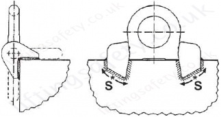
The distance lugs serve as distance measurement for required gap for the root welding. Start of root and fillet weld at point 'S' (see drawing). Before carrying out the fillet weld, carefully clean the root. Possibly filled weld. Fix size 'a' acc. the table 3. The complete weld should be carried out in one heat.
2. Insert ring in welding block. Attach second welding block as tight as possible to the ring, in order to still guarantee moveability of same. Only fasten provisionally.
3. Examine on 180° tilting ability. Possibly make corrections.
4. Weld on second welding block, as described under 1.
- Attention: Do not weld at the pink powder coated, heat treated load ring.
Table 3, Weld size (per welding block):
| Welding Seam Definition | Model | Size | Length | Volume |
 |
VRBK 4 t |
HV 4 + a 3 |
approx. 85mm | approx. 3.2cm³ |
|
VRBK 6,7 t |
HV 5 + a 3 |
approx. 95mm | approx. 6 cm³ | |
| VRBK 10 t | HV 8 + a 4 |
approx. 155mm | approx. 11 cm³ |
This page has now expired please view the new RUD "VRBK-FIX" Weld on Corner Swivel Load Ring Lifting & Lashing Eye.
The welding point for all 90° edges.
The lifting eye, ready for welding VRBK / RBK is prepared for the direct welding at 90° corners at the transport goods. Directly attached at the corner, it saves the double number of lifting eyes. The welding blocks (made of easy weldable material 1.0577+N St. 52-3) have been provided with distance nabs as gap indication for the weld and stamped with the WLL identification number. The ring latch can be tilted by 270°, made of high-tensile material, 100% crack detected and thus overall loadable.
Eye Plate for Corners
- An enhancement of the well-established RBK - series with an over 30% increment of the WLL.
- A forged ring bracket according to EN1677-1, electromagnetically crack detected, pink powder coated and it can be loaded in all directions.
- Even force distribution owing to the two point attachment.
- Low profile sice it can be folded with in an angle range of 270°.
- The welding block for edges is forged out of a good welding material 1.0577+N (St 52-3) and clearly stamped with an identification number for the permissible WLL.
- Welding should only be carried out by qualified persons according to EN 287-1.
Proof Testing
There is no requirement to Proof Test RUD Products, either Bolt or Weldable after Installation if the user instructions for welding are carried out correctly. The welding should be carried out by a suitably qualified and competent welder/person.
The supporting structure, or the load, should be of adequate strength to take the stresses involved and this is the responsibility of the engineering designer or equivalent.
RUD Lifting and Lashing Products are Manufactured and conform to EN 1677. No further Proof Testing in the field is required. In fact it would be considered that the Product had been overloaded if a Load more than the recommended Working Load Limit had been applied.
RUD products should be regularly inspected in line with the requirements of LOLER and as per our user instructions at intervals decided by a competent person.
Table 1, Load Capacities - Metric
| Method of lift |  |
 |
 |
 |
 |
 |
 |
 |
|||
| Number of legs | 1 | 1 | 2 | 2 | 2 | 2 | 2 | 3 and 4 | 3 and 4 | 3 and 4 | |
| Angle of inclination < ß | 0° | 90° | 0° | 90° | 0-45° | 45-60° | unsymmetrical | 0-45° | 45-60° | unsymmetrical | |
| Factor | 1 | 1 | 2 | 2 | 1.4 | 1 | 1 | 2.1 | 1.5 | 1 | |
| Metric Type | WLL in Metric tonnes (total weight) |
||||||||||
| VRBK-FIX 4t | 4t | 4t | 8t | 8t | 5,6t | 4t | 4t | 8,4t | 6t | 4t | |
| VRBK-FIX 6.7t | 6,7t | 6,7t | 13,4t | 13,4t | 9,4t | 6,7t | 6,7t | 14t | 10t | 6,7t | |
| VRBK-FIX 10t | 10t | 10t | 20t | 20t | 14t | 10t | 10t | 21t | 15t | 10t | |
| VRBK-FIX 31.5t | 31.5t | 31.5t | 63t | 63t | 45t | 31.5t | 31.5t | 66.2t | 47.5t | 31.5t | |
| VRBK 50t | 50t | 50t | 100t | 100t | 70t | 50t | 50t | 105t | 75t | 50t | |
Dimensions
| Type | WLL (t) | A (mm) | B (mm) | C (mm) | D (mm) | E (mm) | F (mm) | T (mm) | Weight (kg) |
| VRBK-FIX 4t | 4 | 32 | 14 | 28 | 48 | 140 | 29 | 65 | 1 |
| VRBK-FIX 6.7t | 6.7 | 40 | 20 | 35 | 60 | 180 | 33 | 84 | 2.1 |
| VRBK-FIX 10t | 10 | 52 | 22 | 46 | 65 | 212 | 46 | 94 | 4.4 |
| VRBK-FIX 31.5t | 31.5 | 89 | 42 | 78 | 130 | 394 | 70 | 177 | 24.84 |
| VRBK 50t | 50 | 133 | 70 | 118 | 230 | 626 | 96 | 303 | 76.35 |

User Instructions
1. Reference should be made to German Standards according BGR 500 or other country specific statutory regulations and inspections are to be carried out by competent persons only.
2. Before installing and every use, visually inspect RUD lifting points, paying particular attention to any evidence of weld cracks, corrosion, wear, deformations, etc.
3. The material construction to which the lifting point will be attached should be of adequate strength to withstand forces during lifting without deformation. The contact areas must be free from inpurities, oil, colour, etc.
The material of the forged welding block is S355J2+N (St52-3 1.0577+N), B.S. 4360.50 D or AISI 1019.
4. The lifting points must be positioned on the load in such a way that movement is avoided during lifting.
a.) For single leg lifts, the lifting point should be vertically above the centre of gravity of the load.
b.) For two leg lifts, the lifting points must be equidistant to/or above the centre of gravity of the load.
c.) For three and four leg lifts, the lifting points should be arranged symmetrically around the centre of gravity in the same plane.
5. Load Symmetry:
The working load limits of individual RUD lifting points are calculated using the following formula and are based on symmetrical loading:
|
WLL =
|
G n x cos ß |
WLL = Working Load Limit G = Load Weight (kg) n = Number of load bearing legs ß = Angle of inclination of the chain to the vertical |
The calculation of load bearing legs is as follows:
| No. Legs | Symmectrical | Asymmetrical |
| Two Leg | 2 | 1 |
| Three / Four Leg | 3 | 2 |
(See Table 1)
6. All fittings connected to the VRBK should be free moving. When connecting and disconnecting the lifting means (sling chain), pinches and impacts should be avoided. Damage of the lifting means caused by sharp edges should be avoided as well.
7. The complete design can be annealed stress-free up to <600°C (1100°F) without reduction of WLL.
8. The places where the lifting points are fixed should be marked with colour.
9. At outdoor sites or in case of special danger of corrosion, the welds should only be designed as continuous, fillet welds.
The HV weld at the VRBK guarantees a connection via the whole cross section of the material. This corresponds to a closed weld showing no signs of corrosion.
10. The distance lugs assist in achieving the correct root weld (approx. 3 mm = 0.1 inch). They should not be removed.
11. RUD-Lifting points must not be used under chemical influences such as acids, alkaline solutions and vapours e.g. in pickling baths or hot dip galvanising plants. If this cannot avoided, please contact the manufacturer indicating the concentration, period of penetration and temperature of use.
12. If the lifting points are used exclusively for lashing the value of the working load limit can be doubled.
LC = 2 x WLL
13. After welding, an annual inspection or sooner if conditions dictate should be undertaken by a competent person paying particular attention to the following.
Inspection criteria concerning paragraphs 2 and 13:
- The lifting point should be complete.
- The working load limit and manufacturers stamp should be clearly visible.
- Deformation of the component parts such as body and load ring.
- Mechanical damage, such as notches, particulary in high stress areas.
- Wear should be no more than 10% of cross sectional diameter.
- Evidence of corrosion.
- Evidence of cracks.
- Cracks or other damage to the weld.
Any non-adherence to this advice may result damages of persons and/or materials!
Welding sequence:
The welding should only be carried out according to EN 287 or AWS Standards by an authorised welder.
1. Welding of welding block VRBK.
The distance lugs serve as distance measurement for required gap for the root welding. Start of root and fillet weld at point 'S' (see drawing). Before carrying out the fillet weld, carefully clean the root. Possibly filled weld. Fix size 'a' acc. the table 3. The complete weld should be carried out in one heat.
2. Insert ring in welding block. Attach second welding block as tight as possible to the ring, in order to still guarantee moveability of same. Only fasten provisionally.
3. Examine on 180° tilting ability. Possibly make corrections.
4. Weld on second welding block, as described under 1.
- Attention: Do not weld at the pink powder coated, heat treated load ring.
Table 3, Weld size (per welding block):
| Welding Seam Definition | Model | Size | Length | Volume |
 |
VRBK 4 t |
HV 4 + a 3 |
approx. 85mm | approx. 3.2cm³ |
|
VRBK 6,7 t |
HV 5 + a 3 |
approx. 95mm | approx. 6 cm³ | |
| VRBK 10 t | HV 8 + a 4 |
approx. 155mm | approx. 11 cm³ |
Pricing
Unfortunately this product has been discontinued and/or is no longer available. Please contact us for details on possible alternative products.
Contact Us About This Product
If you wish to receive a quote for this product, please use the 'Pricing' tab above, this form is for general enquiries regarding this product only.
You can also Request a Quote using the Buy/Quote tab above!
You can easily add more than one item to the Quote Request. This is highly recommend as we will be able to suit your needs much more efficiently.
Share this page!

Save this QR code
for use on Smart Phones
