-
Lifting Equipment
 Browse Lifting Equipment Shop
- Chain Hoists
-
Wire Rope Hoists
- Hand Operated Wire Rope Winches and Hoists
- Cable Pullers / Hoists, Wire Rope Manual Operation
- Electric Winches and Hoists, AC (Mains Powered)
- Scaffold Hoists & Accessories
- Overhead Wire Rope Crane Hoists
- Hydraulic Wire Rope Winches & Hoists
- Pneumatic Wire Rope Air Winches / Hoists (Lifting and Pulling)
- Vehicle Mounted Winches
- Tractel Wire Rope & Accessories
-
General Lifting Equipment
- Fibre Slings
- Chain Slings Assemblies & Components
- Lifting and Lashing Chain
- Wire Rope Slings & Assemblies
- Shackles
- Eyebolts and Eyenuts
- Lifting & Pulling Clamps
- Lifting Beams & Spreader Beams
- Precast Concrete Lifting
- Lifting Magnets, Permanent, Battery Electric and Manual
- Runway Beam Monorail Crane Trolleys, Push, Geared & Electric
- Equipment Identification Tags
-
Rigging Equipment
- Crosby Lifting & Rigging
- Master Ring & Load Suspension Eyes
- Lifting & Rigging Hooks
- Turnbuckles & Rigging Screws
- Wire Rope Accessories and Fittings
- Snatch Blocks, Sheave Blocks and Crane Pulley Blocks
- Load Restraint Equipment
- General Rigging Accessories
- Lifting & Rigging Swivels - Eye, Hook & Shackle
- Pulley Sheaves
-
Cranes & Gantry Systems
- Portable Davit Arms and Jib Cranes
- Swing Jib Cranes - Installed Floor & Wall Cranes
- Portable/Mobile Free-standing Swing Jib Cranes
- Aluminium Gantries
- Steel Gantries
- Fixed Steel Gantry Systems
- Shearlegs, Tripods & Quadpods
- Overhead Crane Systems
- Portable Shop-Floor/Workshop/Garage Cranes
- Counterbalance Floor, Workshop Cranes
- Scaffolding Runway Beam Systems
-
Material Handling & Jacking Equipment
- Machinery & Load Moving Skates
- Hydraulic Cylinders & Pumps
- Lifting Jacks
- Manhole Cover Lifters
- Hydraulic Pull Cylinders
- Hand Operated Pallet Trucks, Pump Trucks
- Stacker Trucks, Materials Lifts, Manual and Electric
- Genie and Counterbalance Materials Lifters
- Scissor Lift Tables
- Drum Handling Equipment
- Crane Forks
- Load Weighing Equipment - Load Cells
- Tool Spring Balancers / Load Balancers
- Platform Trucks & Trolleys
-
Fork Lift Truck Attachments
- Fork Mounted Man Riding Baskets
- Environment & Waste Handling Attachments
- Fork Lift Truck Mounted Drum Handling Attachments
- Fork Mounted Jib and Hook Attachments
- Fork Truck Booms & Tines
- Stainless Steel Forklift Attachments
- Forklift Truck Fork Extensions
- Multi Fork Attachments
- Fork Truck Scoop Attachments
- Big Bag Fork Truck Attachment
- Closed Base Coil Support Attachments
- Forklift Fork Protection Sleeves
- Snow Plough Fork Lift Truck Attachments
- Other Forklift Truck & Telehandler Attachments
- Specialist Lifting Equipment
- Access and Safety Related
- Workshop and Shop Floor
- Screwjacks & Actuators
-
Height Safety
 Browse Height Safety Store
-
Fall Arrest and Height Safety Harnesses
- General Use Harnesses EN361
- Work Positioning Harnesses EN361 & EN358
- Rope Access Harnesses
- Rescue Harnesses EN1497 & EN361
- Ladies & Childrens Harnesses
- Hi Vis Jacket/Vest Harnesses
- Welders Harnesses
- ATEX (Anti-Static) Harnesses
- Linesman Harnesses
- Oil Derrick Harnesses
- Sport Climbing Harnesses
- Tree Surgeon Positioning Harnesses
- Sit and Chest Harnesses. EN361 EN356 & EN831
- Work Positioning & Restraint Belts EN358
- Fall Arrest, Restraint and Positioning Lanyards
- Height Safety and Fall Arrest Kits
- Inertia Reels and Retrieval Blocks
- Man-riding Hoists & Rescue Winches
-
Fall Arrest & Man-riding Systems
- Fall Arrest Davit Arms & Posts for Working at Height
- Sala Advanced Davit Arm Systems and Components
- Xtirpa Confined Space Davit Arm Systems and Components
- Abtech Man-riding, Fall Arrest and Rescue Davits and Components
- Man-riding & Rescue Tripods & Quadpods
- Manriding Systems, Baskets and Chairs
- Mobile Fall Arrest Gantries, Systems & Steps
- Rope Guided Fall Arresters (Steel & Synthetic Rope)
- Temporary Horizontal Fall Arrest Lifelines
- Vertical Fall Arrest Systems Permanently Installed
- Horizontal Fall Arrest Systems Permanently Installed
- Manriding Baskets Fork Truck and Overhead Crane
- Tank Side Entry and Vehicle Fall Arrest Systems
- Suspension Seats / Bosuns Chair Working at Height
- Collective Fall Arrest Systems
- Man-Riding Sheave Blocks
- Anchorage Devices
- Karabiners & Connectors
- Rescue, Evacuation & Rope Access
-
General Height Safety Gear
- Height Safety Accessories
- Industrial & Climbing Height Safety Helmets
- Synthetic Height Safety Rope & Anchorage Lines
- Height safety Pulley Wheels For Synthetic & Steel Wire Rope
- Black Height Safety Equipment & PPE
- Hot Work Equipment. Cutting, Grinding & Welding
- Cases, Bags, Backpacks, Holdalls. Height Safety Gear
- Telescopic Extension Pole for Height Safety Applications
- Wind Energy Height Safety Equipment
-
Stainless Steel Fall Arrest Equipment
-
Fall Arrest and Height Safety Harnesses
- Home
- About Us
-
Contact
Get In Touch
- Home/
- Lifting Equipment/
- Workshop and Shop Floor Equipment/
- Hydraulic Workshop Presses/
- Hydraulic Swaging Presses and Machines /
- Crosby Hydraulic Swaging Presses - Range from 500,000kg to 1,500,000kg
Crosby Hydraulic Swaging Presses - Range from 500,000kg to 1,500,000kg
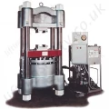
Crosby national hydraulic swaging machine/press.
HSP-2372

The Crosby range of presses are no longer available. Please see our hydraulic swaging press as an alternative.
This is a dual hydraulic system which combines the use of high speed and low pressure to bring dies into position; and the low speed and high pressure necessary for ideal swaging control.
The following features of National Hydraulic Swaging Machines offer a number of advantages for high production sling shops:
- Adjustable tonnage control, so tonnage can be set to match die block Working Load Limit.
- Four column wide stance which provides the operator ample working clearance between columns and a large area for in-process sling storage.
- Vertical swage action which gives an equalized press on the fitting to produce uniform high quality.
- Self locating spring locks snap the shoe-type dies into place for quick set-up and change.
- The National four column wide stance Hydraulic Swaging Machines, each equipped with an up-acting ram, have two side cylinders for fast approach and return of the main ram.
- They come in four swaging capacities.
- 500 ton (4450 kN)
- 1000 ton (8900 kN)
- 1500 ton (13350 kN)
For 1500 Ton Hydraulic Swaging Machines:
- Approximate weight 34,500 lbs. (15.6t)
- Overall height 8 ft. 6 in. (2.6m)
- Fast advance and retract speed.
- Automatic slow, precision swaging speed.

Swaging Machine Capacity Chart for Swage Sleeves, Ferrules & Buttons
| Hydraulic Swaging Machine Size | Swaging Method | Die Size (in.) | Largest Fitting Allowed to be Swaged (in.) | Largest Fitting Allowed to be Swaged (mm) | ||||||||
| S-505 Sleeve | S-506 Sleeve | S-510 Ferrules | S-409 Buttons | S-505 Sleeve | S-506 Sleeve | S-510 Ferrules | S-409 Buttons | |||||
| 500 Ton | Full Die | 2-1/2 x 5 | 1-1/2 | 1-1/4* | 9/16* | 7/8* | 38 | 32* | 14* | 22* | ||
| 4 x 7 | ||||||||||||
| 5 x 7 | ||||||||||||
| 1000 Ton | Full Die | 4 x 7 | 2-1/2 | 1-1/4* | 9/16* | 1-1/4* | 64 | 32* | 14* | 32* | ||
| 5 x 7 | ||||||||||||
| 1500 Ton | Full Die | 5 x 7 | 3-1/2 | 1-1/4* | 9/16* | 1-1/4* | 89 | 32* | 14* | 32* | ||
| 6 x 12 | ||||||||||||
* Largest size fitting available.
Swaging Machine Capacity Chart for S-501 & S-502 Swage Sockets
| Hydraulic Swaging Machine Size | Swaging Method | Die Size (in.) | Largest Fitting Allowed to be Swaged (in.) | Largest Fitting Allowed to be Swaged (mm) |
| 500 Ton | Full Shank | 2-1/2 x 5 | 3/4 | 19 |
| 4 x 7 | ||||
| 5 x 7 | ||||
| Progressive | 4 x 7 | 1-1/4 | 32 | |
| 5 x 7 | ||||
| 1000 Ton | Full Shank | 4 x 7 | 1 | 26 |
| 5 x 7 | ||||
| Progressive | 4 x 7 | 1-1/2 | 38 | |
| 5 x 7 | ||||
| 1500 Ton | Full Shank | 5 x 7 | 1-1/4 | 32 |
| 6 x 12 | ||||
| Progressive | 5 x 7 | 2 | 52 | |
| 6 x 12 |
* Largest size fitting available.
Operational Safety
- NEVER use dies that are cracked, worn or abraded (galled).
- NEVER use dies that have an oversized cavity.
- ALWAYS use a matched set of dies.
- When swaging steel fittings, DO NOT SHIM DIES. Dies for steel fittings must be free to float and align one to the other.
- When swaging aluminum fittings, THE STEEL DIES MUST BE SHIMMED. Shim the side of the die to ensure the proper cavity alignment for flash removal.
- NEVER shim between the dies.
- When swaging Crosby National fittings, use only the proper capacity swaging machine for the size of fitting used (See Swaging Capacity Chart). If the swaging machine capacity exceeds the die block Working Load Limit rating, adjust the swaging machine tonnage to the Working Load Limit shown on the die block being used. See Table 1 for die block Working Load Limit.
- Always use the correct size and type of die for the size wire rope fitting used.
- Always lubricate die faces and cavities with light weight oil.
- Progressive swaging of fittings must be done in accordance with procedure shown in “Swaging Products and Procedures” booklet. Only open channel dies are to be used.
- Stop swaging when the cavity side of both dies touch.
- Make sure part is swaged to the recommended after swage dimensions (See Crosby General Catalog or National Swage Brochure, Die Guide, or Die Chart).
- If a swage fitting other than a Crosby National is used, determine adequacy of the termination by a destructive pull test.
- All swage sockets must be swaged with socket head adjacent to the socket relief (largest radius) on the die.
- For special applications or conditions, contact Crosby National.
Available Die Sizes and Capacities
| Die Size (Height x Width) |
Working Load Limit (WLL) * |
| 2" x 3-1/2" | 200 Ton Mark Series |
| 2-1/2" x 4" | 200 Ton National |
| 2-1/2" x 5" | 500 Ton Mark Series |
| 4" x 7" | 1,200 Ton Mark Series |
| 5" x 7" | 1,500 Ton National |
| Warning |
|---|
|
As advertised in Crosby General Catalogue 2009 Page 47, and previously in Crosby General Catalogue 2006 Page 43.
The Crosby range of presses are no longer available. Please see our hydraulic swaging press as an alternative.
This is a dual hydraulic system which combines the use of high speed and low pressure to bring dies into position; and the low speed and high pressure necessary for ideal swaging control.
The following features of National Hydraulic Swaging Machines offer a number of advantages for high production sling shops:
- Adjustable tonnage control, so tonnage can be set to match die block Working Load Limit.
- Four column wide stance which provides the operator ample working clearance between columns and a large area for in-process sling storage.
- Vertical swage action which gives an equalized press on the fitting to produce uniform high quality.
- Self locating spring locks snap the shoe-type dies into place for quick set-up and change.
- The National four column wide stance Hydraulic Swaging Machines, each equipped with an up-acting ram, have two side cylinders for fast approach and return of the main ram.
- They come in four swaging capacities.
- 500 ton (4450 kN)
- 1000 ton (8900 kN)
- 1500 ton (13350 kN)
For 1500 Ton Hydraulic Swaging Machines:
- Approximate weight 34,500 lbs. (15.6t)
- Overall height 8 ft. 6 in. (2.6m)
- Fast advance and retract speed.
- Automatic slow, precision swaging speed.

Swaging Machine Capacity Chart for Swage Sleeves, Ferrules & Buttons
| Hydraulic Swaging Machine Size | Swaging Method | Die Size (in.) | Largest Fitting Allowed to be Swaged (in.) | Largest Fitting Allowed to be Swaged (mm) | ||||||||
| S-505 Sleeve | S-506 Sleeve | S-510 Ferrules | S-409 Buttons | S-505 Sleeve | S-506 Sleeve | S-510 Ferrules | S-409 Buttons | |||||
| 500 Ton | Full Die | 2-1/2 x 5 | 1-1/2 | 1-1/4* | 9/16* | 7/8* | 38 | 32* | 14* | 22* | ||
| 4 x 7 | ||||||||||||
| 5 x 7 | ||||||||||||
| 1000 Ton | Full Die | 4 x 7 | 2-1/2 | 1-1/4* | 9/16* | 1-1/4* | 64 | 32* | 14* | 32* | ||
| 5 x 7 | ||||||||||||
| 1500 Ton | Full Die | 5 x 7 | 3-1/2 | 1-1/4* | 9/16* | 1-1/4* | 89 | 32* | 14* | 32* | ||
| 6 x 12 | ||||||||||||
* Largest size fitting available.
Swaging Machine Capacity Chart for S-501 & S-502 Swage Sockets
| Hydraulic Swaging Machine Size | Swaging Method | Die Size (in.) | Largest Fitting Allowed to be Swaged (in.) | Largest Fitting Allowed to be Swaged (mm) |
| 500 Ton | Full Shank | 2-1/2 x 5 | 3/4 | 19 |
| 4 x 7 | ||||
| 5 x 7 | ||||
| Progressive | 4 x 7 | 1-1/4 | 32 | |
| 5 x 7 | ||||
| 1000 Ton | Full Shank | 4 x 7 | 1 | 26 |
| 5 x 7 | ||||
| Progressive | 4 x 7 | 1-1/2 | 38 | |
| 5 x 7 | ||||
| 1500 Ton | Full Shank | 5 x 7 | 1-1/4 | 32 |
| 6 x 12 | ||||
| Progressive | 5 x 7 | 2 | 52 | |
| 6 x 12 |
* Largest size fitting available.
Operational Safety
- NEVER use dies that are cracked, worn or abraded (galled).
- NEVER use dies that have an oversized cavity.
- ALWAYS use a matched set of dies.
- When swaging steel fittings, DO NOT SHIM DIES. Dies for steel fittings must be free to float and align one to the other.
- When swaging aluminum fittings, THE STEEL DIES MUST BE SHIMMED. Shim the side of the die to ensure the proper cavity alignment for flash removal.
- NEVER shim between the dies.
- When swaging Crosby National fittings, use only the proper capacity swaging machine for the size of fitting used (See Swaging Capacity Chart). If the swaging machine capacity exceeds the die block Working Load Limit rating, adjust the swaging machine tonnage to the Working Load Limit shown on the die block being used. See Table 1 for die block Working Load Limit.
- Always use the correct size and type of die for the size wire rope fitting used.
- Always lubricate die faces and cavities with light weight oil.
- Progressive swaging of fittings must be done in accordance with procedure shown in “Swaging Products and Procedures” booklet. Only open channel dies are to be used.
- Stop swaging when the cavity side of both dies touch.
- Make sure part is swaged to the recommended after swage dimensions (See Crosby General Catalog or National Swage Brochure, Die Guide, or Die Chart).
- If a swage fitting other than a Crosby National is used, determine adequacy of the termination by a destructive pull test.
- All swage sockets must be swaged with socket head adjacent to the socket relief (largest radius) on the die.
- For special applications or conditions, contact Crosby National.
Available Die Sizes and Capacities
| Die Size (Height x Width) |
Working Load Limit (WLL) * |
| 2" x 3-1/2" | 200 Ton Mark Series |
| 2-1/2" x 4" | 200 Ton National |
| 2-1/2" x 5" | 500 Ton Mark Series |
| 4" x 7" | 1,200 Ton Mark Series |
| 5" x 7" | 1,500 Ton National |
| Warning |
|---|
|
As advertised in Crosby General Catalogue 2009 Page 47, and previously in Crosby General Catalogue 2006 Page 43.
Pricing
Unfortunately this product has been discontinued and/or is no longer available. Please contact us for details on possible alternative products.
Contact Us About This Product
If you wish to receive a quote for this product, please use the 'Pricing' tab above, this form is for general enquiries regarding this product only.
You can also Request a Quote using the Buy/Quote tab above!
You can easily add more than one item to the Quote Request. This is highly recommend as we will be able to suit your needs much more efficiently.
Share this page!

Save this QR code
for use on Smart Phones


