-
Lifting Equipment
 Browse Lifting Equipment Shop
- Chain Hoists
-
Wire Rope Hoists
- Hand Operated Wire Rope Winches and Hoists
- Cable Pullers / Hoists, Wire Rope Manual Operation
- Electric Winches and Hoists, AC (Mains Powered)
- Scaffold Hoists & Accessories
- Overhead Wire Rope Crane Hoists
- Hydraulic Wire Rope Winches & Hoists
- Pneumatic Wire Rope Air Winches / Hoists (Lifting and Pulling)
- Vehicle Mounted Winches
- Tractel Wire Rope & Accessories
-
General Lifting Equipment
- Fibre Slings
- Chain Slings Assemblies & Components
- Lifting and Lashing Chain
- Wire Rope Slings & Assemblies
- Shackles
- Eyebolts and Eyenuts
- Lifting & Pulling Clamps
- Lifting Beams & Spreader Beams
- Precast Concrete Lifting
- Lifting Magnets, Permanent, Battery Electric and Manual
- Runway Beam Monorail Crane Trolleys, Push, Geared & Electric
- Equipment Identification Tags
-
Rigging Equipment
- Crosby Lifting & Rigging
- Master Ring & Load Suspension Eyes
- Lifting & Rigging Hooks
- Turnbuckles & Rigging Screws
- Wire Rope Accessories and Fittings
- Snatch Blocks, Sheave Blocks and Crane Pulley Blocks
- Load Restraint Equipment
- General Rigging Accessories
- Lifting & Rigging Swivels - Eye, Hook & Shackle
- Pulley Sheaves
-
Cranes & Gantry Systems
- Portable Davit Arms and Jib Cranes
- Swing Jib Cranes - Installed Floor & Wall Cranes
- Portable/Mobile Free-standing Swing Jib Cranes
- Aluminium Gantries
- Steel Gantries
- Fixed Steel Gantry Systems
- Shearlegs, Tripods & Quadpods
- Overhead Crane Systems
- Portable Shop-Floor/Workshop/Garage Cranes
- Counterbalance Floor, Workshop Cranes
- Scaffolding Runway Beam Systems
-
Material Handling & Jacking Equipment
- Machinery & Load Moving Skates
- Hydraulic Cylinders & Pumps
- Lifting Jacks
- Manhole Cover Lifters
- Hydraulic Pull Cylinders
- Hand Operated Pallet Trucks, Pump Trucks
- Stacker Trucks, Materials Lifts, Manual and Electric
- Genie and Counterbalance Materials Lifters
- Scissor Lift Tables
- Gas Cylinder Handling Equipment
- Drum Handling Equipment
- Crane Forks
- Load Weighing Equipment - Load Cells
- Tool Spring Balancers / Load Balancers
- Platform Trucks & Trolleys
-
Fork Lift Truck Attachments
- Fork Mounted Man Riding Baskets
- Environment & Waste Handling Attachments
- Fork Lift Truck Mounted Drum Handling Attachments
- Fork Mounted Jib and Hook Attachments
- Fork Truck Booms & Tines
- Stainless Steel Forklift Attachments
- Forklift Truck Fork Extensions
- Multi Fork Attachments
- Fork Truck Scoop Attachments
- Big Bag Fork Truck Attachment
- Closed Base Coil Support Attachments
- Forklift Fork Protection Sleeves
- Snow Plough Fork Lift Truck Attachments
- Other Forklift Truck & Telehandler Attachments
- Specialist Lifting Equipment
- Access and Safety Related
-
Workshop and Shop Floor
- Drum Handling Equipment
- Scissor Lift Tables
- Hydraulic Cylinders & Pumps
- General Garage / Workshop Tools, Accessory Kits and Handling Tools
- Gas Cylinder Handling Equipment
- Hydraulic Lifting Jacks - Toe Jacks and Bottle Jacks, Handle operated
- Mechanical Lifting Jacks (Not Hydraulic)
- Hydraulic Workshop Presses
- Hydraulic Tools & Accessories
- Screwjacks & Actuators
-
Height Safety
 Browse Height Safety Store
-
Fall Arrest and Height Safety Harnesses
- General Use Harnesses EN361
- Work Positioning Harnesses EN361 & EN358
- Rope Access Harnesses
- Rescue Harnesses EN1497 & EN361
- Ladies & Childrens Harnesses
- Hi Vis Jacket/Vest Harnesses
- Welders Harnesses
- ATEX (Anti-Static) Harnesses
- Linesman Harnesses
- Oil Derrick Harnesses
- Sport Climbing Harnesses
- Tree Surgeon Positioning Harnesses
- Sit and Chest Harnesses. EN361 EN356 & EN831
- Work Positioning & Restraint Belts EN358
- Fall Arrest, Restraint and Positioning Lanyards
- Height Safety and Fall Arrest Kits
- Inertia Reels and Retrieval Blocks
- Man-riding Hoists & Rescue Winches
-
Fall Arrest & Man-riding Systems
- Fall Arrest Davit Arms & Posts for Working at Height
- Sala Advanced Davit Arm Systems and Components
- Xtirpa Confined Space Davit Arm Systems and Components
- Abtech Man-riding, Fall Arrest and Rescue Davits and Components
- Man-riding & Rescue Tripods & Quadpods
- Manriding Systems, Baskets and Chairs
- Mobile Fall Arrest Gantries, Systems & Steps
- Rope Guided Fall Arresters (Steel & Synthetic Rope)
- Temporary Horizontal Fall Arrest Lifelines
- Vertical Fall Arrest Systems Permanently Installed
- Horizontal Fall Arrest Systems Permanently Installed
- Manriding Baskets Fork Truck and Overhead Crane
- Tank Side Entry and Vehicle Fall Arrest Systems
- Suspension Seats / Bosuns Chair Working at Height
- Collective Fall Arrest Systems
- Man-Riding Sheave Blocks
- Anchorage Devices
- Karabiners & Connectors
- Rescue, Evacuation & Rope Access
-
General Height Safety Gear
- Height Safety Accessories
- Industrial & Climbing Height Safety Helmets
- Synthetic Height Safety Rope & Anchorage Lines
- Height safety Pulley Wheels For Synthetic & Steel Wire Rope
- Black Height Safety Equipment & PPE
- Hot Work Equipment. Cutting, Grinding & Welding
- Cases, Bags, Backpacks, Holdalls. Height Safety Gear
- Telescopic Extension Pole for Height Safety Applications
- Wind Energy Height Safety Equipment
-
Stainless Steel Fall Arrest Equipment
-
Fall Arrest and Height Safety Harnesses
- Home
- About Us
-
Contact
Get In Touch
- Home/
- Lifting Equipment/
- Cranes; Mobile, Portable and Fixed/
- Portable Davit Arms and Jib Cranes/
- Portable/Mobile Free-standing Jib Cranes/
- Mobile Man-riding Suspension Jibs for Temporary Suspended Platforms - 150kg to 1000kg SWL
Mobile Man-riding Suspension Jibs for Temporary Suspended Platforms - 150kg to 1000kg SWL
Portable Suspension Jib / TP-3496
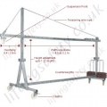
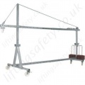


This Page has now expired. Please Contact us with your requirements for a superseding model or suitable alternative.
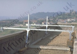
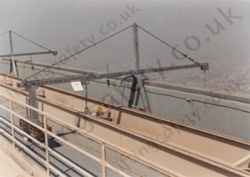
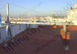
The mobile portable suspension jibs allow very fast access to the building facades using many types of temporary platforms.
Portable suspension jibs are robust and easy to assemble and to dismantle. They represent the ideal solution for nearly every flat roof, especially when the parapet is not strong enough to hold a load. The stability of the jibs is provided by counterweights. no roof penetration is required, reach (cantilever distance), height and SWL to our customers requirements.
Please contact our sales team for advise and / or a quotation.
Important: Not certified for rope access, however previously known to be used by companies for rope access, but under their own risk assessment.
Standard Configurations
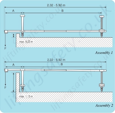
System 1
Two assemblies are possible:
- For use on parapets not exceeding 0.23 m.
- Allow the jib to pass over obstacles up to 1.13 m high.
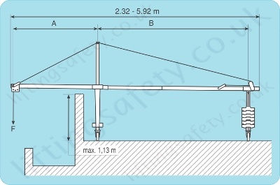
System 2
Model with reinforcing bracket and guy wire rope, recommended for longer overhangs (A) or heavy loads.
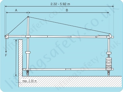
System 3
Model with:
- Two additional height adjusters fixed on the mobile front and rear cross bars.
- An additional telescopic jib to reinforce the structure.
- Two crossbar extensions at the front to increase its stability.
This model is able to pass over obstacles up to 2 m high.
 |
 |
 |
|
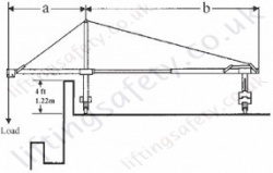
System Setup 1 Telescopic beam mounted directly on front and rear crossbars can be moved on Castor wheels. This assembly is to be used where parapet height does not exceed 1 foot (0.3 m). |
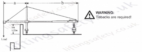
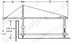
System Setup 2 A height adjuster fitted to the front crossbar lets the overhead telescopic beam pass over a 4 ft (1.22 m) high obstacles (chimneys, ventilation shafts, parapets, etc.).
|
System Setup 3 Fitted with reinforcement brace and tensioning wire rope, this model is recommended for longer overhangs or very heavy suspended loads (e.g pulley-block mounted on suspension wire rope, etc.). |
|
(a) - 0.4 m to 1.6 m (b) - 1.4 m to 5.2 m (c) - upto 0.3 m (1 ft). |
(a) - 0.4 m to 2.0 m (b) - 1.4 m to 5.2 m (c) - upto 1.22 m (4 ft). |
(a) - 0.4 m to 2.0 m (b) - 1.4 m to 5.2 m (c) - upto 2.0 m (6 ft 8 in). |
|
Usable adjustments: (a) - overhang, (b) - distance behind the fulcrum & (c) - height adjustment. *** Please note, these units are fully adjustable between the measurements above, but effect the required amount of counterweights you will need to use with the system, either refer to the tables below our use the pricing tab for a fully automated configuration tool. *** |
||
Maximum Permited Overhang (A)
| Working Load Limit (WLL)* | Portable Suspension Jib |
||
| System 1 | System 2 |
System 3 |
|
| 150kg | 1600mm | 2000mm | 2000mm |
| 300kg | 1000mm | 2000mm | 2000mm |
| 400kg | 800mm | 2000mm | 2000mm |
| 500kg | 800mm | 2000mm | 2000mm |
| 800kg | - | 1200mm | 1200mm |
| 1000kg | - | 1200mm | - |
*"Working load limit" (WLL) should be taken to mean the nominal capacity of the hoist and not the actual suspended load. The loads indicated above apply to the capacities of Tirak hoists.
Calculation of Counterweight
The tables below illustrate the number of counterweights needed for the different capacities (WLL) depending upon the overhang (A) and the distance (B) behind the fulcrum line. It is always better to have the maximum distance (B) behind the fulcrum line, depending of course of the space available, to reduce the number of counterweights and consequently the wheel loads on the roof. Furthermore this makes assembly and dismantling much easier.The total length of the telescopic jib (A + B) should not exceed 5.60 m.
Maximum Suspended Load: 150kg
| Overhang | Distance behind the fulcrum line B (m) | RA max¹ (kg) | Rb max² (kg) | ||||||||||||
| A | metre | 1.4 | 1.6 | 1.8 | 2.0 | 2.4 | 2.8 | 3.2 | 3.6 | 4.0 | 4.4 | 5.0 | 5.2 | ||
| Without Guy Rope (system 1) |
0.4 | 4 | 3 | 2 | 2 | 1 | 1 | 0 | 0 | 0 | 0 | 0 | 0 | 190 | 170 |
| 0.6 | 6 | 5 | 5 | 4 | 3 | 1 | 1 | 1 | 0 | 0 | 0 | - | 200 | 190 | |
| 0.8 | 9 | 8 | 7 | 6 | 5 | 3 | 2 | 2 | 1 | 1 | - | - | 210 | 220 | |
| 1.0 | 12 | 10 | 9 | 8 | 5 | 4 | 3 | 3 | 2 | 2 | - | - | 220 | 240 | |
| 1.2 | 14 | 12 | 11 | 9 | 7 | 5 | 5 | 4 | 3 | 3 | - | - | 250 | 260 | |
| 1.4 | 17 | 14 | 13 | 10 | 8 | 7 | 6 | 5 | 4 | - | - | - | 270 | 290 | |
| 1.6 | 19 | 17 | 14 | 12 | 10 | 8 | 7 | 6 | 5 | - | - | - | 290 | 300 | |
| With Guy Rope (system 2 & 3) |
1.8 | 22 | 18 | 17 | 14 | 12 | 10 | 8 | 7 | - | - | - | - | 320 | 330 |
| 2.0 | 24 | 21 | 18 | 16 | 13 | 11 | 9 | 8 | - | - | - | - | 340 | 340 | |
| N = Number of counterweights required per jib. | |||||||||||||||
Maximum Suspended Load: 300kg
| Overhang | Distance behind the fulcrum line B (m) | RA max¹ (kg) | Rb max² (kg) | ||||||||||||
| A | metre | 1.4 | 1.6 | 1.8 | 2.0 | 2.4 | 2.8 | 3.2 | 3.6 | 4.0 | 4.4 | 5.0 | 5.2 | ||
| Without Guy Rope (system 1) | 0.4 | 9 | 7 | 6 | 6 | 4 | 4 | 2 | 1 | 1 | 1 | 0 | 0 | 300 | 240 |
| 0.6 | 14 | 12 | 11 | 9 | 7 | 5 | 4 | 4 | 3 | 2 | 2 | - | 310 | 290 | |
| 0.8 | 19 | 17 | 15 | 13 | 11 | 8 | 7 | 6 | 5 | 4 | - | - | 340 | 340 | |
| 1.0 | 24 | 21 | 19 | 17 | 12 | 10 | 9 | 8 | 7 | 6 | - | - | 380 | 390 | |
| With Guy Rope (system 2 & 3) | 1.2 | 30 | 26 | 23 | 20 | 16 | 13 | 11 | 10 | 9 | 8 | - | - | 420 | 460 |
| 1.4 | 35 | 30 | 27 | 23 | 19 | 16 | 14 | 12 | 10 | - | - | - | 450 | 51 | |
| 1.6 | - | 35 | 30 | 27 | 22 | 19 | 16 | 14 | 12 | - | - | - | 470 | 490 | |
| 1.8 | - | - | 34 | 31 | 25 | 21 | 18 | 16 | - | - | - | - | 480 | 470 | |
| 2.0 | - | - | - | 34 | 28 | 24 | 21 | 18 | - | - | - | - | 490 | 460 | |
| N = Number of counterweights required per jib. | |||||||||||||||
Maximum Suspended Load: 400kg
| Overhang | Distance behind the fulcrum line B (m) | RA max¹ (kg) | Rb max² (kg) | ||||||||||||
| A | metre | 1.4 | 1.6 | 1.8 | 2.0 | 2.4 | 2.8 | 3.2 | 3.6 | 4.0 | 4.4 | 5.0 | 5.2 | ||
| Without Guy Rope (system 1) | 0.4 | 12 | 10 | 9 | 8 | 6 | 5 | 3 | 3 | 2 | 2 | 1 | 1 | 360 | 270 |
| 0.6 | 19 | 17 | 15 | 13 | 10 | 7 | 6 | 6 | 5 | 4 | 3 | - | 400 | 350 | |
| 0.8 | 26 | 23 | 20 | 18 | 15 | 11 | 10 | 8 | 7 | 6 | - | - | 440 | 430 | |
| With Guy Rope (system 2 & 3) | 1.0 | 33 | 29 | 25 | 23 | 17 | 15 | 13 | 11 | 10 | 9 | - | - | 490 | 500 |
| 1.2 | - | 35 | 31 | 27 | 22 | 18 | 16 | 14 | 12 | 11 | - | - | 510 | 510 | |
| 1.4 | - | - | 36 | 31 | 26 | 22 | 19 | 17 | 15 | - | - | - | 530 | 510 | |
| 1.6 | - | - | - | 36 | 30 | 26 | 22 | 19 | 17 | - | - | - | 550 | 500 | |
| 1.8 | - | - | - | - | 34 | 29 | 25 | 22 | - | - | - | - | 550 | 470 | |
| 2.0 | - | - | - | - | - | 33 | 28 | 25 | - | - | - | - | 540 | 450 | |
| N = Number of counterweights required per jib. | |||||||||||||||
Maximum Suspended Load: 500kg
| Overhang | Distance behind the fulcrum line B (m) | RA max¹ (kg) | Rb max² (kg) | ||||||||||||
| A | metre | 1.4 | 1.6 | 1.8 | 2.0 | 2.4 | 2.8 | 3.2 | 3.6 | 4.0 | 4.4 | 5.0 | 5.2 | ||
| Without Guy Rope (system 1) | 0.4 | 16 | 13 | 12 | 10 | 8 | 7 | 5 | 4 | 3 | 3 | 2 | 2 | 430 | 320 |
| 0.6 | 24 | 21 | 19 | 17 | 13 | 10 | 9 | 8 | 7 | 6 | 5 | - | 490 | 410 | |
| 0.8 | 33 | 29 | 25 | 23 | 19 | 15 | 13 | 11 | 10 | 9 | - | - | 540 | 510 | |
| With Guy Rope (system 2 & 3) | 1.0 | - | 36 | 32 | 29 | 22 | 19 | 16 | 14 | 13 | 11 | - | - | 570 | 530 |
| 1.2 | - | - | - | 35 | 28 | 23 | 20 | 18 | 16 | 14 | - | - | 590 | 500 | |
| 1.4 | - | - | - | - | 33 | 28 | 24 | 21 | 19 | - | - | - | 590 | 470 | |
| 1.6 | - | - | - | - | - | 32 | 28 | 25 | 22 | - | - | - | 590 | 450 | |
| 1.8 | - | - | - | - | - | - | 32 | 28 | - | - | - | - | 590 | 450 | |
| 2.0 | - | - | - | - | - | - | 36 | 31 | - | - | - | - | 610 | 500 | |
| N = Number of counterweights required per jib. | |||||||||||||||
Maximum Suspended Load: 800kg
| Overhang | Distance behind the fulcrum line B (m) | RA max¹ (kg) | Rb max² (kg) | ||||||||||||
| A | metre | 1.4 | 1.6 | 1.8 | 2.0 | 2.4 | 2.8 | 3.2 | 3.6 | 4.0 | 4.4 | 5.0 | 5.2 | ||
| With Guy Rope (system 2 & 3) | 0.4 | 26 | 22 | 20 | 18 | 14 | 12 | 9 | 8 | 7 | 6 | 5 | 5 | 670 | 450 |
| 0.6 | - | 35 | 31 | 27 | 22 | 18 | 15 | 14 | 12 | 11 | 9 | - | 740 | 540 | |
| 0.8 | - | - | - | - | 31 | 25 | 22 | 19 | 17 | 15 | - | - | 750 | 460 | |
| 1.0 | - | - | - | - | - | 32 | 28 | 24 | 22 | 19 | - | - | 770 | 460 | |
| 1.2 | - | - | - | - | - | - | 34 | 30 | 27 | 24 | - | - | 790 | 480 | |
| N = Number of counterweights required per jib. | |||||||||||||||
Maximum Suspended Load: 1000kg
| Overhang | Distance behind the fulcrum line B (m) | RA max¹ (kg) | Rb max² (kg) | ||||||||||||
| A | metre | 1.4 | 1.6 | 1.8 | 2.0 | 2.4 | 2.8 | 3.2 | 3.6 | 4.0 | 4.4 | 5.0 | 5.2 | ||
| With Guy Rope (system 2 & 3) | 0.4 | 33 | 28 | 25 | 22 | 18 | 16 | 12 | 11 | 9 | 8 | 7 | 7 | 830 | 540 |
| 0.6 | - | - | - | 35 | 28 | 23 | 20 | 18 | 16 | 14 | 12 | - | 880 | 530 | |
| 0.8 | - | - | - | - | - | 32 | 28 | 24 | 22 | 19 | - | - | 890 | 470 | |
| 1.0 | - | - | - | - | - | - | 35 | 31 | 28 | 25 | - | - | 920 | 500 | |
| 1.2 | - | - | - | - | - | - | - | - | 34 | 30 | - | - | 910 | 480 | |
| N = Number of counterweights required per jib. | |||||||||||||||
**(¹) Ra max = dynamic reaction per front wheel, with the platform suspended (dynamic factor = 1,25). For final reaction per front wheel (operating load multiplied by a factor of 3): multiply the Ra max. values by approximately 2.2.
(²) Rb max = maximum reaction per rear wheel, with the platform on the ground.
Safety and Assembly
- Fall protection is required on all suspended platforms.
- Only persons familiar with the rigging techniques and the equipment are authorized to assemble our Suspension Beams.
- Check daily the condition of the various components Use only OEM parts
- Before assembling the counter-weighted beams, always make sure that the roof and the parapet are capable of carrying the loads applied by the suspended loads. If necessary, refer to static calculations.
- On all roofs, place planks or channel under the wheels to safeguard the roof to obtain better load distribution.
- Space permitting, extend the telescopic beams up to its maximum length in order to reduce the required number of counterweights and ease
assembly and dismantling. - When the assembly is finished, lock the brakes of the castor wheels.
- Before moving the beams around on the roof, lower the platform to ground level and slacken all wire ropes.
CAUTION
Almost 80% of all accidents occurring during work on suspended scaffolds are caused by incorrectly installed SUSPENSION SYSTEMS or incorrectly calculated counterweights. Ensure lifting device is tested before every use when using with this system.
Assembly
Portable Suspension Beams have been designed specifically for use with our Suspended Scaffolds. They can be used equally well for suspending any other type of suspended scaffold that consist of standard elements thus permitting the following basic assemblies:
System setup 1
Telescopic beam mounted directly on front and rear crossbars can be moved on castor wheels. This assembly is to be used where parapet height does not exceed 1 foot (0.3 m).
System setup 2
A height adjuster fitted to the front crossbar lets the overhead telescopic beam pass over a 4 ft (1.22 m) high obstacles (chimneys, ventilation shafts, parapets, etc.).
System setup 3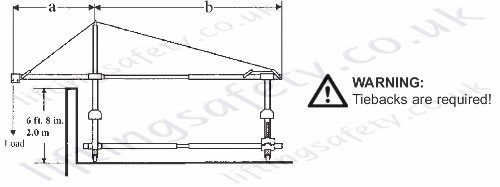
Fitted with reinforcement brace and tensioning wire rope, this model is recommended for longer overhangs or very heavy suspended loads (e.g pulley-block mounted on suspension wire rope, etc.).
Spare Parts
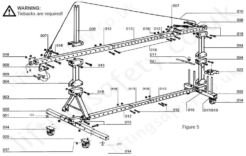
| Item | Code | Description | Portafix 'A' | Portafix 'B' | Portafix 'C' | Weight | |
| lbs | kg | ||||||
| 001 | 7787 | Front Crossbar | 1 | 1 | 1 | 27.8 | 12.6 |
| 002 | 7767 | Rear counterweight crossbar | 1 | 1 | 1 | 37.9 | 17.2 |
| 003 | 7807 | Front height adjuster | - | 1 | 1 | 41.4 | 18.8 |
| 004 | 7797 | Rear height adjuster | 1 | 1 | 1 | 29.3 | 13.3 |
| 005 | 7827 | Reinforcing bracket | - | - | 1 | 19.6 | 8.9 |
| 006 | 17497 | Rigging stirrup | 2 | 2 | 2 | 1.1 | 0.5 |
| 007 | 7847 | Anchor stirrup | - | - | 4 | 4.9 | 2.2 |
| 008 | 17477 | Reversing stirrup | - | - | 1 | 5.3 | 2.4 |
| 009 | 19387 | Anchor pin + spring clip | 2 | 2 | 2 | 1.1 | 0.5 |
| 010 | 7817 | Wire rope tensioner (turn buckle) | - | - | 1 | 15.2 | 6.9 |
| 011 | 35806 | Padlock | 1 | 1 | 1 | - | - |
| 012 | 35345 | Outer beam section | 2 | 2 | 2 | 42.3 | 19.2 |
| 013 | 35325 | Intermediate beam section | 1 | 1 | 1 | 49.6 | 22.5 |
| 014 | 20096 | Castor w/wheel brake | 4 | 4 | 4 | 8.8 | 4.0 |
| 015 | 10806 | Bolt TH M18 x 140 DIN 931 8.8 Z | 6 | 10 | 11 | - | - |
| 016 | 10786 | Bolt TH M18 x 120 DIN 931 8.8 Z | 4 | 4 | 9 | - | - |
| 017 | 3566 | Bolt TH M10 x 25 DIN 933 8.8 Z | 17 | 17 | 17 | - | - |
| 018 | 10796 | Nut NYLOC M18 DIN 985 Z | 10 | 14 | 20 | - | - |
| 019 | 8006 | Nut NYLOC H M10 DIN 985 Z | 17 | 17 | 17 | - | - |
| 020 | RBT0013B | Front crossbar extension | 0 | 0 | 2 | 20.0 | 9.0 |
| 021 | 19937 | Counterweight locking bar | 1 | 1 | 1 | 2.0 | 0.9 |
| 022 | 3378 | Cast iron counterweight | as a function of the load (max. 36) | 55.1 | 25.0 | ||
| 023 | RBILJ1080B | Screw Jack Stabilizer | 0 | 0 | 2 | 35 | 16 |
This Page has now expired. Please Contact us with your requirements for a superseding model or suitable alternative.
The mobile portable suspension jibs allow very fast access to the building facades using many types of temporary platforms.
Portable suspension jibs are robust and easy to assemble and to dismantle. They represent the ideal solution for nearly every flat roof, especially when the parapet is not strong enough to hold a load. The stability of the jibs is provided by counterweights. no roof penetration is required, reach (cantilever distance), height and SWL to our customers requirements.
Please contact our sales team for advise and / or a quotation.
Important: Not certified for rope access, however previously known to be used by companies for rope access, but under their own risk assessment.


Standard Configurations

System 1
Two assemblies are possible:
- For use on parapets not exceeding 0.23 m.
- Allow the jib to pass over obstacles up to 1.13 m high.

System 2
Model with reinforcing bracket and guy wire rope, recommended for longer overhangs (A) or heavy loads.

System 3
Model with:
- Two additional height adjusters fixed on the mobile front and rear cross bars.
- An additional telescopic jib to reinforce the structure.
- Two crossbar extensions at the front to increase its stability.
This model is able to pass over obstacles up to 2 m high.
 |
 |
 |
|
System Setup 1 Telescopic beam mounted directly on front and rear crossbars can be moved on Castor wheels. This assembly is to be used where parapet height does not exceed 1 foot (0.3 m). |
System Setup 2 A height adjuster fitted to the front crossbar lets the overhead telescopic beam pass over a 4 ft (1.22 m) high obstacles (chimneys, ventilation shafts, parapets, etc.).
|
System Setup 3 Fitted with reinforcement brace and tensioning wire rope, this model is recommended for longer overhangs or very heavy suspended loads (e.g pulley-block mounted on suspension wire rope, etc.). |
|
(a) - 0.4 m to 1.6 m (b) - 1.4 m to 5.2 m (c) - upto 0.3 m (1 ft). |
(a) - 0.4 m to 2.0 m (b) - 1.4 m to 5.2 m (c) - upto 1.22 m (4 ft). |
(a) - 0.4 m to 2.0 m (b) - 1.4 m to 5.2 m (c) - upto 2.0 m (6 ft 8 in). |
|
Usable adjustments: (a) - overhang, (b) - distance behind the fulcrum & (c) - height adjustment. *** Please note, these units are fully adjustable between the measurements above, but effect the required amount of counterweights you will need to use with the system, either refer to the tables below our use the pricing tab for a fully automated configuration tool. *** |
||
Maximum Permited Overhang (A)
| Working Load Limit (WLL)* | Portable Suspension Jib |
||
| System 1 | System 2 |
System 3 |
|
| 150kg | 1600mm | 2000mm | 2000mm |
| 300kg | 1000mm | 2000mm | 2000mm |
| 400kg | 800mm | 2000mm | 2000mm |
| 500kg | 800mm | 2000mm | 2000mm |
| 800kg | - | 1200mm | 1200mm |
| 1000kg | - | 1200mm | - |
*"Working load limit" (WLL) should be taken to mean the nominal capacity of the hoist and not the actual suspended load. The loads indicated above apply to the capacities of Tirak hoists.
Calculation of Counterweight
The tables below illustrate the number of counterweights needed for the different capacities (WLL) depending upon the overhang (A) and the distance (B) behind the fulcrum line. It is always better to have the maximum distance (B) behind the fulcrum line, depending of course of the space available, to reduce the number of counterweights and consequently the wheel loads on the roof. Furthermore this makes assembly and dismantling much easier.The total length of the telescopic jib (A + B) should not exceed 5.60 m.
Maximum Suspended Load: 150kg
| Overhang | Distance behind the fulcrum line B (m) | RA max¹ (kg) | Rb max² (kg) | ||||||||||||
| A | metre | 1.4 | 1.6 | 1.8 | 2.0 | 2.4 | 2.8 | 3.2 | 3.6 | 4.0 | 4.4 | 5.0 | 5.2 | ||
| Without Guy Rope (system 1) |
0.4 | 4 | 3 | 2 | 2 | 1 | 1 | 0 | 0 | 0 | 0 | 0 | 0 | 190 | 170 |
| 0.6 | 6 | 5 | 5 | 4 | 3 | 1 | 1 | 1 | 0 | 0 | 0 | - | 200 | 190 | |
| 0.8 | 9 | 8 | 7 | 6 | 5 | 3 | 2 | 2 | 1 | 1 | - | - | 210 | 220 | |
| 1.0 | 12 | 10 | 9 | 8 | 5 | 4 | 3 | 3 | 2 | 2 | - | - | 220 | 240 | |
| 1.2 | 14 | 12 | 11 | 9 | 7 | 5 | 5 | 4 | 3 | 3 | - | - | 250 | 260 | |
| 1.4 | 17 | 14 | 13 | 10 | 8 | 7 | 6 | 5 | 4 | - | - | - | 270 | 290 | |
| 1.6 | 19 | 17 | 14 | 12 | 10 | 8 | 7 | 6 | 5 | - | - | - | 290 | 300 | |
| With Guy Rope (system 2 & 3) |
1.8 | 22 | 18 | 17 | 14 | 12 | 10 | 8 | 7 | - | - | - | - | 320 | 330 |
| 2.0 | 24 | 21 | 18 | 16 | 13 | 11 | 9 | 8 | - | - | - | - | 340 | 340 | |
| N = Number of counterweights required per jib. | |||||||||||||||
Maximum Suspended Load: 300kg
| Overhang | Distance behind the fulcrum line B (m) | RA max¹ (kg) | Rb max² (kg) | ||||||||||||
| A | metre | 1.4 | 1.6 | 1.8 | 2.0 | 2.4 | 2.8 | 3.2 | 3.6 | 4.0 | 4.4 | 5.0 | 5.2 | ||
| Without Guy Rope (system 1) | 0.4 | 9 | 7 | 6 | 6 | 4 | 4 | 2 | 1 | 1 | 1 | 0 | 0 | 300 | 240 |
| 0.6 | 14 | 12 | 11 | 9 | 7 | 5 | 4 | 4 | 3 | 2 | 2 | - | 310 | 290 | |
| 0.8 | 19 | 17 | 15 | 13 | 11 | 8 | 7 | 6 | 5 | 4 | - | - | 340 | 340 | |
| 1.0 | 24 | 21 | 19 | 17 | 12 | 10 | 9 | 8 | 7 | 6 | - | - | 380 | 390 | |
| With Guy Rope (system 2 & 3) | 1.2 | 30 | 26 | 23 | 20 | 16 | 13 | 11 | 10 | 9 | 8 | - | - | 420 | 460 |
| 1.4 | 35 | 30 | 27 | 23 | 19 | 16 | 14 | 12 | 10 | - | - | - | 450 | 51 | |
| 1.6 | - | 35 | 30 | 27 | 22 | 19 | 16 | 14 | 12 | - | - | - | 470 | 490 | |
| 1.8 | - | - | 34 | 31 | 25 | 21 | 18 | 16 | - | - | - | - | 480 | 470 | |
| 2.0 | - | - | - | 34 | 28 | 24 | 21 | 18 | - | - | - | - | 490 | 460 | |
| N = Number of counterweights required per jib. | |||||||||||||||
Maximum Suspended Load: 400kg
| Overhang | Distance behind the fulcrum line B (m) | RA max¹ (kg) | Rb max² (kg) | ||||||||||||
| A | metre | 1.4 | 1.6 | 1.8 | 2.0 | 2.4 | 2.8 | 3.2 | 3.6 | 4.0 | 4.4 | 5.0 | 5.2 | ||
| Without Guy Rope (system 1) | 0.4 | 12 | 10 | 9 | 8 | 6 | 5 | 3 | 3 | 2 | 2 | 1 | 1 | 360 | 270 |
| 0.6 | 19 | 17 | 15 | 13 | 10 | 7 | 6 | 6 | 5 | 4 | 3 | - | 400 | 350 | |
| 0.8 | 26 | 23 | 20 | 18 | 15 | 11 | 10 | 8 | 7 | 6 | - | - | 440 | 430 | |
| With Guy Rope (system 2 & 3) | 1.0 | 33 | 29 | 25 | 23 | 17 | 15 | 13 | 11 | 10 | 9 | - | - | 490 | 500 |
| 1.2 | - | 35 | 31 | 27 | 22 | 18 | 16 | 14 | 12 | 11 | - | - | 510 | 510 | |
| 1.4 | - | - | 36 | 31 | 26 | 22 | 19 | 17 | 15 | - | - | - | 530 | 510 | |
| 1.6 | - | - | - | 36 | 30 | 26 | 22 | 19 | 17 | - | - | - | 550 | 500 | |
| 1.8 | - | - | - | - | 34 | 29 | 25 | 22 | - | - | - | - | 550 | 470 | |
| 2.0 | - | - | - | - | - | 33 | 28 | 25 | - | - | - | - | 540 | 450 | |
| N = Number of counterweights required per jib. | |||||||||||||||
Maximum Suspended Load: 500kg
| Overhang | Distance behind the fulcrum line B (m) | RA max¹ (kg) | Rb max² (kg) | ||||||||||||
| A | metre | 1.4 | 1.6 | 1.8 | 2.0 | 2.4 | 2.8 | 3.2 | 3.6 | 4.0 | 4.4 | 5.0 | 5.2 | ||
| Without Guy Rope (system 1) | 0.4 | 16 | 13 | 12 | 10 | 8 | 7 | 5 | 4 | 3 | 3 | 2 | 2 | 430 | 320 |
| 0.6 | 24 | 21 | 19 | 17 | 13 | 10 | 9 | 8 | 7 | 6 | 5 | - | 490 | 410 | |
| 0.8 | 33 | 29 | 25 | 23 | 19 | 15 | 13 | 11 | 10 | 9 | - | - | 540 | 510 | |
| With Guy Rope (system 2 & 3) | 1.0 | - | 36 | 32 | 29 | 22 | 19 | 16 | 14 | 13 | 11 | - | - | 570 | 530 |
| 1.2 | - | - | - | 35 | 28 | 23 | 20 | 18 | 16 | 14 | - | - | 590 | 500 | |
| 1.4 | - | - | - | - | 33 | 28 | 24 | 21 | 19 | - | - | - | 590 | 470 | |
| 1.6 | - | - | - | - | - | 32 | 28 | 25 | 22 | - | - | - | 590 | 450 | |
| 1.8 | - | - | - | - | - | - | 32 | 28 | - | - | - | - | 590 | 450 | |
| 2.0 | - | - | - | - | - | - | 36 | 31 | - | - | - | - | 610 | 500 | |
| N = Number of counterweights required per jib. | |||||||||||||||
Maximum Suspended Load: 800kg
| Overhang | Distance behind the fulcrum line B (m) | RA max¹ (kg) | Rb max² (kg) | ||||||||||||
| A | metre | 1.4 | 1.6 | 1.8 | 2.0 | 2.4 | 2.8 | 3.2 | 3.6 | 4.0 | 4.4 | 5.0 | 5.2 | ||
| With Guy Rope (system 2 & 3) | 0.4 | 26 | 22 | 20 | 18 | 14 | 12 | 9 | 8 | 7 | 6 | 5 | 5 | 670 | 450 |
| 0.6 | - | 35 | 31 | 27 | 22 | 18 | 15 | 14 | 12 | 11 | 9 | - | 740 | 540 | |
| 0.8 | - | - | - | - | 31 | 25 | 22 | 19 | 17 | 15 | - | - | 750 | 460 | |
| 1.0 | - | - | - | - | - | 32 | 28 | 24 | 22 | 19 | - | - | 770 | 460 | |
| 1.2 | - | - | - | - | - | - | 34 | 30 | 27 | 24 | - | - | 790 | 480 | |
| N = Number of counterweights required per jib. | |||||||||||||||
Maximum Suspended Load: 1000kg
| Overhang | Distance behind the fulcrum line B (m) | RA max¹ (kg) | Rb max² (kg) | ||||||||||||
| A | metre | 1.4 | 1.6 | 1.8 | 2.0 | 2.4 | 2.8 | 3.2 | 3.6 | 4.0 | 4.4 | 5.0 | 5.2 | ||
| With Guy Rope (system 2 & 3) | 0.4 | 33 | 28 | 25 | 22 | 18 | 16 | 12 | 11 | 9 | 8 | 7 | 7 | 830 | 540 |
| 0.6 | - | - | - | 35 | 28 | 23 | 20 | 18 | 16 | 14 | 12 | - | 880 | 530 | |
| 0.8 | - | - | - | - | - | 32 | 28 | 24 | 22 | 19 | - | - | 890 | 470 | |
| 1.0 | - | - | - | - | - | - | 35 | 31 | 28 | 25 | - | - | 920 | 500 | |
| 1.2 | - | - | - | - | - | - | - | - | 34 | 30 | - | - | 910 | 480 | |
| N = Number of counterweights required per jib. | |||||||||||||||
**(¹) Ra max = dynamic reaction per front wheel, with the platform suspended (dynamic factor = 1,25). For final reaction per front wheel (operating load multiplied by a factor of 3): multiply the Ra max. values by approximately 2.2.
(²) Rb max = maximum reaction per rear wheel, with the platform on the ground.
Safety and Assembly
- Fall protection is required on all suspended platforms.
- Only persons familiar with the rigging techniques and the equipment are authorized to assemble our Suspension Beams.
- Check daily the condition of the various components Use only OEM parts
- Before assembling the counter-weighted beams, always make sure that the roof and the parapet are capable of carrying the loads applied by the suspended loads. If necessary, refer to static calculations.
- On all roofs, place planks or channel under the wheels to safeguard the roof to obtain better load distribution.
- Space permitting, extend the telescopic beams up to its maximum length in order to reduce the required number of counterweights and ease
assembly and dismantling. - When the assembly is finished, lock the brakes of the castor wheels.
- Before moving the beams around on the roof, lower the platform to ground level and slacken all wire ropes.
CAUTION
Almost 80% of all accidents occurring during work on suspended scaffolds are caused by incorrectly installed SUSPENSION SYSTEMS or incorrectly calculated counterweights. Ensure lifting device is tested before every use when using with this system.
Assembly
Portable Suspension Beams have been designed specifically for use with our Suspended Scaffolds. They can be used equally well for suspending any other type of suspended scaffold that consist of standard elements thus permitting the following basic assemblies:
System setup 1
Telescopic beam mounted directly on front and rear crossbars can be moved on castor wheels. This assembly is to be used where parapet height does not exceed 1 foot (0.3 m).
System setup 2
A height adjuster fitted to the front crossbar lets the overhead telescopic beam pass over a 4 ft (1.22 m) high obstacles (chimneys, ventilation shafts, parapets, etc.).
System setup 3
Fitted with reinforcement brace and tensioning wire rope, this model is recommended for longer overhangs or very heavy suspended loads (e.g pulley-block mounted on suspension wire rope, etc.).
Spare Parts

| Item | Code | Description | Portafix 'A' | Portafix 'B' | Portafix 'C' | Weight | |
| lbs | kg | ||||||
| 001 | 7787 | Front Crossbar | 1 | 1 | 1 | 27.8 | 12.6 |
| 002 | 7767 | Rear counterweight crossbar | 1 | 1 | 1 | 37.9 | 17.2 |
| 003 | 7807 | Front height adjuster | - | 1 | 1 | 41.4 | 18.8 |
| 004 | 7797 | Rear height adjuster | 1 | 1 | 1 | 29.3 | 13.3 |
| 005 | 7827 | Reinforcing bracket | - | - | 1 | 19.6 | 8.9 |
| 006 | 17497 | Rigging stirrup | 2 | 2 | 2 | 1.1 | 0.5 |
| 007 | 7847 | Anchor stirrup | - | - | 4 | 4.9 | 2.2 |
| 008 | 17477 | Reversing stirrup | - | - | 1 | 5.3 | 2.4 |
| 009 | 19387 | Anchor pin + spring clip | 2 | 2 | 2 | 1.1 | 0.5 |
| 010 | 7817 | Wire rope tensioner (turn buckle) | - | - | 1 | 15.2 | 6.9 |
| 011 | 35806 | Padlock | 1 | 1 | 1 | - | - |
| 012 | 35345 | Outer beam section | 2 | 2 | 2 | 42.3 | 19.2 |
| 013 | 35325 | Intermediate beam section | 1 | 1 | 1 | 49.6 | 22.5 |
| 014 | 20096 | Castor w/wheel brake | 4 | 4 | 4 | 8.8 | 4.0 |
| 015 | 10806 | Bolt TH M18 x 140 DIN 931 8.8 Z | 6 | 10 | 11 | - | - |
| 016 | 10786 | Bolt TH M18 x 120 DIN 931 8.8 Z | 4 | 4 | 9 | - | - |
| 017 | 3566 | Bolt TH M10 x 25 DIN 933 8.8 Z | 17 | 17 | 17 | - | - |
| 018 | 10796 | Nut NYLOC M18 DIN 985 Z | 10 | 14 | 20 | - | - |
| 019 | 8006 | Nut NYLOC H M10 DIN 985 Z | 17 | 17 | 17 | - | - |
| 020 | RBT0013B | Front crossbar extension | 0 | 0 | 2 | 20.0 | 9.0 |
| 021 | 19937 | Counterweight locking bar | 1 | 1 | 1 | 2.0 | 0.9 |
| 022 | 3378 | Cast iron counterweight | as a function of the load (max. 36) | 55.1 | 25.0 | ||
| 023 | RBILJ1080B | Screw Jack Stabilizer | 0 | 0 | 2 | 35 | 16 |
Pricing
Unfortunately this product has been discontinued and/or is no longer available. Please contact us for details on possible alternative products.
Contact Us About This Product
If you wish to receive a quote for this product, please use the 'Pricing' tab above, this form is for general enquiries regarding this product only.
You can also Request a Quote using the Buy/Quote tab above!
You can easily add more than one item to the Quote Request. This is highly recommend as we will be able to suit your needs much more efficiently.
Share this page!

Save this QR code
for use on Smart Phones
