-
Lifting Equipment
 Browse Lifting Equipment Shop
- Chain Hoists
-
Wire Rope Hoists
- Hand Operated Wire Rope Winches and Hoists
- Cable Pullers / Hoists, Wire Rope Manual Operation
- Electric Winches and Hoists, AC (Mains Powered)
- Scaffold Hoists & Accessories
- Overhead Wire Rope Crane Hoists
- Hydraulic Wire Rope Winches & Hoists
- Pneumatic Wire Rope Air Winches / Hoists (Lifting and Pulling)
- Vehicle Mounted Winches
- Tractel Wire Rope & Accessories
-
General Lifting Equipment
- Fibre Slings
- Chain Slings Assemblies & Components
- Lifting and Lashing Chain
- Wire Rope Slings & Assemblies
- Shackles
- Eyebolts and Eyenuts
- Lifting & Pulling Clamps
- Lifting Beams & Spreader Beams
- Precast Concrete Lifting
- Lifting Magnets, Permanent, Battery Electric and Manual
- Runway Beam Monorail Crane Trolleys, Push, Geared & Electric
- Equipment Identification Tags
-
Rigging Equipment
- Crosby Lifting & Rigging
- Master Ring & Load Suspension Eyes
- Lifting & Rigging Hooks
- Turnbuckles & Rigging Screws
- Wire Rope Accessories and Fittings
- Snatch Blocks, Sheave Blocks and Crane Pulley Blocks
- Load Restraint Equipment
- General Rigging Accessories
- Lifting & Rigging Swivels - Eye, Hook & Shackle
- Pulley Sheaves
-
Cranes & Gantry Systems
- Portable Davit Arms and Jib Cranes
- Swing Jib Cranes - Installed Floor & Wall Cranes
- Portable/Mobile Free-standing Swing Jib Cranes
- Aluminium Gantries
- Steel Gantries
- Fixed Steel Gantry Systems
- Shearlegs, Tripods & Quadpods
- Overhead Crane Systems
- Portable Shop-Floor/Workshop/Garage Cranes
- Counterbalance Floor, Workshop Cranes
- Scaffolding Runway Beam Systems
-
Material Handling & Jacking Equipment
- Machinery & Load Moving Skates
- Hydraulic Cylinders & Pumps
- Lifting Jacks
- Manhole Cover Lifters
- Hydraulic Pull Cylinders
- Hand Operated Pallet Trucks, Pump Trucks
- Stacker Trucks, Materials Lifts, Manual and Electric
- Genie and Counterbalance Materials Lifters
- Scissor Lift Tables
- Drum Handling Equipment
- Crane Forks
- Load Weighing Equipment - Load Cells
- Tool Spring Balancers / Load Balancers
- Platform Trucks & Trolleys
-
Fork Lift Truck Attachments
- Fork Mounted Man Riding Baskets
- Environment & Waste Handling Attachments
- Fork Lift Truck Mounted Drum Handling Attachments
- Fork Mounted Jib and Hook Attachments
- Fork Truck Booms & Tines
- Stainless Steel Forklift Attachments
- Forklift Truck Fork Extensions
- Multi Fork Attachments
- Fork Truck Scoop Attachments
- Big Bag Fork Truck Attachment
- Closed Base Coil Support Attachments
- Forklift Fork Protection Sleeves
- Snow Plough Fork Lift Truck Attachments
- Other Forklift Truck & Telehandler Attachments
- Specialist Lifting Equipment
- Access and Safety Related
- Workshop and Shop Floor
- Screwjacks & Actuators
-
Height Safety
 Browse Height Safety Store
-
Fall Arrest and Height Safety Harnesses
- General Use Harnesses EN361
- Work Positioning Harnesses EN361 & EN358
- Rope Access Harnesses
- Rescue Harnesses EN1497 & EN361
- Ladies & Childrens Harnesses
- Hi Vis Jacket/Vest Harnesses
- Welders Harnesses
- ATEX (Anti-Static) Harnesses
- Linesman Harnesses
- Oil Derrick Harnesses
- Sport Climbing Harnesses
- Tree Surgeon Positioning Harnesses
- Sit and Chest Harnesses. EN361 EN356 & EN831
- Work Positioning & Restraint Belts EN358
- Fall Arrest, Restraint and Positioning Lanyards
- Height Safety and Fall Arrest Kits
- Inertia Reels and Retrieval Blocks
- Man-riding Hoists & Rescue Winches
-
Fall Arrest & Man-riding Systems
- Fall Arrest Davit Arms & Posts for Working at Height
- Sala Advanced Davit Arm Systems and Components
- Xtirpa Confined Space Davit Arm Systems and Components
- Abtech Man-riding, Fall Arrest and Rescue Davits and Components
- Man-riding & Rescue Tripods & Quadpods
- Manriding Systems, Baskets and Chairs
- Mobile Fall Arrest Gantries, Systems & Steps
- Rope Guided Fall Arresters (Steel & Synthetic Rope)
- Temporary Horizontal Fall Arrest Lifelines
- Vertical Fall Arrest Systems Permanently Installed
- Horizontal Fall Arrest Systems Permanently Installed
- Manriding Baskets Fork Truck and Overhead Crane
- Tank Side Entry and Vehicle Fall Arrest Systems
- Suspension Seats / Bosuns Chair Working at Height
- Collective Fall Arrest Systems
- Man-Riding Sheave Blocks
- Anchorage Devices
- Karabiners & Connectors
- Rescue, Evacuation & Rope Access
-
General Height Safety Gear
- Height Safety Accessories
- Industrial & Climbing Height Safety Helmets
- Synthetic Height Safety Rope & Anchorage Lines
- Height safety Pulley Wheels For Synthetic & Steel Wire Rope
- Black Height Safety Equipment & PPE
- Hot Work Equipment. Cutting, Grinding & Welding
- Cases, Bags, Backpacks, Holdalls. Height Safety Gear
- Telescopic Extension Pole for Height Safety Applications
- Wind Energy Height Safety Equipment
-
Stainless Steel Fall Arrest Equipment
-
Fall Arrest and Height Safety Harnesses
- Home
- About Us
-
Contact
Get In Touch
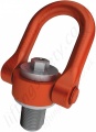
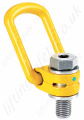
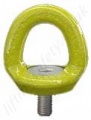
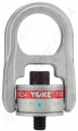
RUD "VRS" & "VRS-F" Starpoint Rotating Eyebolts. WLL Range from 0.1 tonne to 12.0 tonne
Starpoint Eyebolts - RUD VRS with option of Metric, Metric Fine or UNC thread
Model:
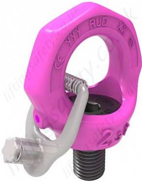
RUD VRS / VRSF / SVE-54