


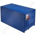
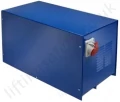
Lifting Equipment Power Converters for Electric Hoists and Winches Converts 240v single phase to 415v 3 phase
Electrical voltage converters specifically designed for use with hoists and winches.
PCF-3341
This page has expired. We no longer supply this product range.
Using one of our voltage converters / transformers you can easily run a 3 phase hoist on a single phase power supply.

By using the SELS electric power converter any 3 Phase 415v electric hoist or winch can be powered from a single phase 230 volt power supply. The advantage being that 3Ph hoists have a better duty cycle and are much better suited for repetitive use applications such as in production environments, or any situation that means that the hoist will more frequently for example where there is a great height of lift. Electric motors on 3ph lifting and pulling hoists and winches cope better in these situation than 1Ph motors and they take longer to overheat. When there is a 3Ph power supply we recommend in most situations to use 415v rated lifting equipment though when only a 230v supply is available the power converter will allow you to use more heavy duty 3Ph lifting gear. As a general rule 230v electric hoists are not available supplied with an integrated power travel trolley and can not be supplied 2 speed lift or travel; by using our power converters all of these features become available when the end user only have a single phase power supply obtainable.
In our opinion our range of voltage converters are the best available from a UK manufacturer. They feature a 600% overload capability, electrically noiseless sealed solid state electronic switching, and a three year guarantee***. Models of 3kW or less also feature a symmetric neutral as standard - the first time this has ever been offered in the world.
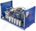
Single to 3 phase converters (commonly misnamed as 3 phase transformers or inverters) provide three phase power from a single phase supply. We achieve the 3 phase power conversion using an internal motor-generator with 600% overload capability and no electromechanical contacts.
Technical Specifications
| Rotary Converters | Maximum multi-motor loadª (continuous - not peak) | Maximum single motor loadª (continuous - not peak) | Min. loadª | Dimensions (installed) | Weight | 220/240 V Supply; | |||
| Fuse or circuit breaker* | Cable size* | ||||||||
| hp | kW | hp | kW | hp | W x D x H, mm | kg | Amps | mm2 | |
| C 1.5 | 2.0 | 1.50 | 2.0 | 1.50 | 0.00 | 650 x 325 x 305 | 41 | 13 A | 1.5 |
| C 2.2 | 3.0 | 2.20 | 3.0 | 2.25 | 0.00 | 650 x 325 x 305 | 50 | 15 A | 2.5 |
| C 3 | 4.0 | 3.00 | 4.0 | 3.00 | 0.00 | 650 x 325 x 305 | 56 | 20 A | 2.5 |
| C 4 | 5.4 | 4.00 | 5.4 | 4.00 | 0.00 | 813 x 396 x 400 | 80 | 32 A | 4.0 |
| C 6 | 8.0 | 6.00 | 8.0 | 6.00 | 0.00 | 813 x 396 x 400 | 105 | 40 A | 6.0 |
| C 8 | 10.7 | 8.00 | 10.7 | 8.00 | 0.00 | 813 x 396 x 400 | 140 | 50 A | 8.0 |
| C 12 | 16.1 | 12.00 | 16.1 | 12.00 | 0.00 | 800 x 780 x 520 | 195 | 75 A | 16.0 |
| C 16 | 21.5 | 16.00 | 21.5 | 16.00 | 0.00 | 800 x 780 x 520 | 220 | 100 A | 25.0 |
| G 6 | 8 | 6 | - | - | - | 810 x 400 x 400 | 105 | 40 A | 6.0 |
| G 8 | 10.7 | 8 | - | - | - | 810 x 400 x 400 | 140 | 50 A | 10.0 |
| G 12 | 16.1 | 12 | - | - | - | 800 x 1000 x 850 | 195 | 75 A | 16.0 |
| G 16 | 21.5 | 16 | - | - | - | 800 x 1000 x 850 | 220 | 100 A | 25.0 |
|
ª Typical continuous duty load specifications. Actual specifications may vary slightly depending upon customer application - please contact us for advice. |
|||||||||
All our components come from reputable suppliers who manufacture to international or British Standards, some of whom produce components to our unique designs and who have been working with us for decades. Our products comply with current EMC regulations and are built to specifications and standards that are within the EEC Electrical Safety Directives and carry the CE mark. A certificate of conformity is available on request.
Our converters are housed in a powder-coated finish mild steel enclosure. Standard fittings on the smaller Boosters (up to 6kW) include a safety switch/fuse (MCB); a 5 pin 16 Amp x 415 Volt socket; and a terminal block for hard wiring in a 415 Volt ring main if required. Standard fittings on the larger Boosters (8kW and above) include a single phase isolator, a stop/start button, and an overload (MCB); a 5 pin 16 Amp x 415 Volt socket; and a terminal block for hard wiring in a 415 Volt ring main.
All units are well labeled and supplied with installation and user instructions. Boost converters can run at full load with balanced phases ± 5%. Boost has the flexibility to produce special units to meet unusual customer needs.
The size of the phase converter unit will normally depend on the HP or kW of the motor(s) or other loads to be run:
- No motor larger than the rating of the converter must be used.
- More than one motor may be run simultaneously from a Boost converter provided that the total multi-motor rating is not greater than the converter rating, e.g. a 3 HP motor will require a 4 HP converter; a 5 HP motor and a 4 HP motor may be run simultaneously from one 12 HP converter.
General Features
A three phase converter will supply a number and variety of loads at full performance. Unlike 'static' phase converters, they are not limited to driving a single motor, nor do they limit the motor's torque or have a lower limit to output power. This range of 3 phase converters has the unique feature of electronically switching up to 600 % of rated power for up to 10 seconds for 'hard starting' or momentary overload. Solid state switching takes place as the power waveform crosses zero, minimising electromagnetic interference. There are no electromechanical contacts to wear out or open at full voltage (emitting interference).
Understanding & Selecting a Single to Three phase Converter
This page aims to help intelligent selection of a 3 phase converter. Specifically, which model might work best for your machines, and some things to look for as you compare models. We will try to make you as well informed as possible in a short time. But please feel free to contact us with any technical questions before you make your final selection.
Contents
- Basic principles of Electricity.
- Why 3-phase is better.
- 3 phase power supply.
- Three phase conversion methodology.
- Capacitors.
- Operation.
- Some construction details.
- What to expect.
- Balanced voltages; interpreting current balance.
- Three phase voltages.
- Pivots and other technical Information.
Electricity
The magnetic field that causes a motor to rotate is produced from the electricity supplied by the power company, called the utility in many countries. Electricity is measured in terms of voltage and current. Using the analogy of water supply, voltage is analogous to pressure, and current is analogous to flow. Voltage is measured in Volts (V). Current is measured in Amperes (A). Power is Voltage multiplied by current, measured in Watts (W) or thousands of watts, kilowatts (kW). One kW is equivalent to 1.34 horsepower.
Electricity is distributed as Alternating Current (AC). Whereas a battery has two terminals, one that is always positive (+), and one that is always negative (-), AC changes, or alternates, from positive (+) to negative (-) at a set frequency, usually 50 times a second (50 cycles per second or Hertz or Hz).
At the power company's local distribution transformer, voltage is reduced from 11,000V to either 230V and Neutral (Ground) or to 3 phases, red, yellow and blue, each 230V to neutral. The voltage measured between each pair of phases will then be 400V.
There are still some variations found in different countries, e.g. 220V (380V between phases) and 240V (415V between phases). USA, Canada and some South American countries distribute single phase 110-127 V, i.e. 190-220V between phases.
In an electric motor, as the electrical polarity on the AC line changes (from + to -), the magnetic poles in the motor change from north to south in relation to the rotor poles, causing the motor to rotate.
With each change in polarity the voltage rises and falls as a wave, passing through zero voltage, called a zero crossing. Each time the voltage rises, either above or below zero crossing, the motor receives power, much as a motor vehicle receives power each time the engine fires.
Why three-phase is better
Using the motor vehicle analogy, the pulsing power from an internal combustion engine needs to be smoothed by a heavy flywheel. Single-phase AC has somewhat similar characteristics, although less marked. The zero crossings produce a subtle but persistent power interruption. Single-phase motors are not usually produced above 5 hp.
Two power peaks (positive and negative) every 1/50th second seems smooth enough. A motor running at 3000 rpm, i.e. 50 revs/s receives only 2 power strokes per revolution. This is analogous to the crank in a 4-cylinder, 4-stroke internal combustion engine. With three phase electrical power a motor running at 3000 rpm receives 6 power strokes per revolution, analogous to a 12-cylinder internal combustion engine. This is only an approximate analogy because the electrical power peaks are more gently rounded than the sharp pulses from exploding fuel but it serves to illustrate the point.
3-phase power supply
Users in rural or remote locations (or anywhere in the UK and Ireland) will find that a 3-phase supply is not easily obtained from their local power company. Installation costs in the UK range from 3000 to 72000 pounds. Unless you are in an urban area within a country where a 3-phase service is shared among many customers, installation costs will be prohibitive.
Even in such a fortunate situation, there are many cases where it is inconvenient to extend the 3-phase supply to the point where it is needed. For example, a large building might well have 3-phase supplied to the basement for the building services. If a motor or a computer installation is on an upper floor and work to extend the supply to it has to be undertaken out of normal working hours, this can produce an unacceptable lead time and cost. The situation is worse if the unit to be supplied is moved around the building frequently.
Users have also been surprised to learn that even if the power company has already installed 3 phases, many extra costs, in the form of daily or monthly line charges, "demand" billing based on peak use and higher kilowatt-hour rates, serve to drive up the price of three-phase supplies far higher than the investment required for a 1ph to 3ph converter.
Because such converters work from the secondary side of the power grid (after the utility-supplier's street or pole transformer), installation is simple. Only three-phase loads are applied to the converter. All existing lighting and other wiring to single-phase loads remains unchanged.
As for converter costs, a 4kW model can cost less than 700 GBP plus VAT (1000 euro or $US 1200). It can be installed in a few minutes and its operating cost is virtually zero.
A Booster™ D or E can be connected to your three-phase loads in about 30 minutes. It can operate any combination of motors, heaters, welders, or 3-phase rectifiers (AC to DC).
This you buy once, and may expect it to last 30 years and more with virtually no maintenance and repairs ! With an operating cost of only about 5% of the operated load it is easy to see that phase conversion is one of the best industrial bargains available.
The next step is to determine the model that is best suited to your needs.
Three phase conversion methodology
To the best of our knowledge, most manufacturers still use timers and mechanical contactors. As this method is not free from maintenance and cannot provide hard-start capabilities without oversizing the converter and/or use of a manual boost button, we have developed the solid state converter based on modern capacitor-switching technologies. These products are being used in remote parts of Australia and New Zealand !
Capacitors
A capacitor can be viewed as temporary electrical storage. Alternating Voltage is delayed as the capacitor is charged. Capacitors have been used to operate three-phase motors on single-phase power for decades. In this method, the two single-phase wires are connected to two of the inputs of a three-phase motor. A capacitor is then connected between one of the single-phase inputs and the third terminal of the motor.
A motor requires about 5 times as much current to start as it does to run, so a capacitor-type single to three-phase converter must have some means of switching a large group of capacitors in and out during motor starting.
This solid-state switch is a high-voltage high-current semiconductor, tested at 2200V and, in the smallest converter, withstanding short circuit currents of 2300 A. Switching is precisely triggered at zero voltage and zero current transitions in order to minimise stress on components, to the motor and to the supply line.
The trigger and switch circuitry, using state-of-the-art CMOS logic, is protected against any kind of moisture, dust, electric noise, magnetic and electrostatic fields, overvoltage and undervoltage.
Operation
The smaller generates all three phases internally. Such a device distributes three-phase power to multiple motors and to many machines.
Electric power is injected into a running motor-generator, resulting in three useful sine wave phases separated by 120 degrees as with utility power. The equipment may then be started and stopped in any combination up to the Booster´s total load capacity. Any type of three-phase load may be operated with a these converters.
This unique single to three-phase converter will produce up to 600% of maximum continuous power. For how many minutes ? Don´t worry, if the start-up time of a motor is too long, the motor rated fuse in your fuse box will blow or the overload protection in your machine will trip. A Booster™ is a very tough device, not easily overloaded.
The output of a voltage booster is nearly as high as utility power, as long as the single phase supply is stable enough to provide short high power bursts required by the booster, i.e. when starting motors or when motors are under excessive load. When output currents rise to 600%, the input current will momentarily go up to 600% of the maximum input current as well.
If your supply cable is not rated sufficiently, severe voltage drop may occur at the input side. The same relative voltage drop will be found at the converter output. Motors will then not accelerate as fast as they should and will not cope with excessive loads as well as they would with stable voltages. When connecting a Booster™, always use a heavier single-phase supply cable than actually needed. In case of extreme hard-starts found with applications like refrigeration systems, metal lathes, hydraulic systems or wheel balancers, install very good wires and cables or compensate for input wire losses by selecting a voltage convertor with about 30% more power.
Some Construction Details
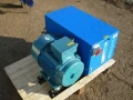
The internal motor-generator shares many characteristics with the three-phase motors it operates. There is a set of stationary field coils, or stator, that determines the magnetic poles in the electrical steel of the rotary. These coils and their poles have 120° spacing to produce a uniform three-phase wave form. A squirrel-cage type rotor produces the poles of the rotating magnetic field. Very much like a rotating transformer. The rotor has a good bearing support in aluminium end-bells. The rotor-to-stator air gap is smaller than in many motors, since a magnetic "flux" that produces three-phase voltages must pass this air gap.
The phase-shifted current from the capacitors is absorbed by the electrical steel of the rotary motor-generator, then distributed in a three-phase waveform that is usable by any type of equipment. The type of motor-generator used in a Booster™ A has the highest efficiency found on the market. It is free of maintenance and it is of the type used as generators in wind turbines.
Capacitors in the internal capacitor bank are switched when needed. Switching is performed at zero crossing transitions of each sine wave. Using this method, there is no stress to any part. Polypropylene capacitors are the guarantee for long life expectation (10000 hours at normal temperatures).
Due to the zero crossing switching, EMC, or electromagnetic radiation, is kept low and always within limits in all countries. These voltage boosters complies with EMC regulations in all European countries.
The compact and smart switch-controller is the key to their performance. Inputs and outputs are filtered against incoming spikes, noises and other disturbances. The controller measures output conditions and senses the need for high currents to accelerate external motors. It also contains the high voltage and high current power switches activating capacitors in the Booster´s capacitor bank. They are designed to withstand at least 2200 Volts (all versions), well above the highest peaks found in urban or rural areas.
The CMOS logic is completely embedded in Epoxy resin giving lifetime protection against dust and moisture.
Life expectancy is practically unlimited.
What to expect
Compared with three phase supply from your local power company, a voltage convertor is a viable compromise, even coping with motor hard-starts. This is stated to prevent unwarranted expectations of the equipment. Converters have weaknesses and strengths which should be considered before a purchase is made.
As mentioned earlier, These units also have a low purchase cost, far lower than the cost to bring three-phase to your premises via power lines. Operating cost is very low, about five percent of the electrical cost of the operated load.
A standard, multi-motor installation will not quite balance each line's power as well as a utility-supplied, three-wire, three-phase system.
The quality of the booster´s three-phase output depends a lot on the quality and stability of the single phase input line. Since output currents sometimes increase to 600% of the maximum continuous currents, the input lines are also loaded with higher currents.
High input currents may result in input voltage drops. When motors are starting under load, we have seen voltage drops from 230V down to 170V. Because the nature of a voltage booster is a transformer, this will result in a voltage drop at the three phase output from 3 x 400V to about 3 x 280V. Under these conditions, motors will not accelerate as fast as they should.
If the time period of excessive input currents is extended, either the input fuse will blow, or the protective overload switch in your equipment will trip.
To overcome these problems, it pays to install oversized cables between your fuse box and the Booster´s input. If the voltage drop of the supply side is reduced, motors on the output side will accelerate faster.
Low input or output voltages will not do any harm to the converter. They only reduce the overall efficiency.
Compared with the power company's grid, a voltage convertor might not maintain close voltage balance over a wide range of operation. Line-to-line three-phase voltages may vary somewhat with changing loads. If you have voltage-sensitive equipment such as some computerised machine tools (CNC).
By analysing the strengths and weaknesses of each option, utility three-phase or a converter, you minimise your disappointments with either. Utility supplied three-phase power brings higher electrical costs than single to three-phase converter power because someone has to pay the purchase and maintenance cost of the extra lines and extra street-transformers, out in all weathers.
When you don't need three-phase, you turn it off and you're not paying any line charges. It is 100 percent tax deductible for your business, and you can take it to a new location.
Balanced Voltages; Interpreting Current Balance
Balancing a three-phase load is important to avoid one phase being overloaded while the other two are not contributing their share. Excessive unbalanced power will harm a motor if the imbalance is so great as to overheat the windings.
Operated on a multi-motor system is very efficient, although not quite 100 %. As with a motor vehicle engine, it has a typical load at which it operates at highest efficiency.
The ideal load for one of these units is about 20-90% of it´s maximum load. Since most machines are designed to utilise less than 100% of the motor's power, a booster will probably run most efficiently when the power range of a booster matches the input power range of a machine or motor.
In case of hard-start conditions, some manufacturers suggest using a single to three-phase converter about 2-3 times the size of the operated motor. This is not necessary with these boosters.
Three phase voltages and neutral
The voltages between the three output connectors will be about 1.73 times (square root of 3) higher than the 230 V input, i.e. about 400 volts.
4 to 64kw converters produce a "delta voltage". If voltages are measured between one of the phases and ground, different values are found. This is because of the step-up input transformer configuration.
All large motors and machines use the voltage between the three phases. Therefore, if you have a 4 to 64kW converter, do not connect a load between a phase and Neutral. Should output voltage at light load be needed between one of the phases and Neutral, use L3 only. L3 is directly connected to the single phase input line and may be used for any kind of external control circuitry or other general purpose.
Converters from 1.1 to 3 produce a "star voltage" as is normal for small motors and machines. The star point is connected to neutral so single phase control circuits or other light loads can be connected between any phase and neutral. If there are three such circuits then it is advisable to connect one between each phase and neutral to balance the load.
Pivots and other technical Information
If your pivot operation is a "windshield wiper" configuration, that is, a pivot that runs a partial circle and then reverses direction, then you should choose a one of our units. Under normal pivot operation, only one-half the motors will start at once. However, when a pivot is reversed, all the motors that were "off" when stopped will now start. Thus, a 10 tower pivot may reverse, restarting 7 or 8 motors, and exceed a normal converter's capacity.
The converter should be mounted as close to the single phase service as possible to minimise the heavier single-phase wiring required. 32, 48 and 64 kW Boosters™ are equipped with a soft-starting feature that reduces the starting inrush of the converter to approximately half of normal on start-up to prevent line disturbance.
All thse converters are high-efficiency models. Power consumed by this type of converter itself will amount to approximately 5% of the operated load.
Economic justification
Many properties are, for economic reasons, only connected to one of the three phases of utility power available at the nearest distribution transformer. A single phase supply line was the cheaper option when the premises were built. Similarly, large buildings with 3 phase supplied might still have locations where it is uneconomic or inconvenient to run 3 phase wiring.
If three-phase equipment is to be used, a simple comparison can be made: compare the cost for providing three-phase supply (e.g. distribution transformer, power lines, monthly line charges) with the price of a single to three-phase converter.
Example applications
Woodworking workshops:
- Saw, Spindle moulder, Planer, Thicknesser, Belt sander
- Band saw, CNC machine, Foursider, Tenoner, Mortiser
- Combination machine, Wood turning lathe, Sander, Router
- Borer, Edge-bander, dust extractor.
Metalworking workshops:
Lathe, Drill, Milling machine, Grinder, Saw, Polisher, Shaper, Guillotines, Press, Welder.
Vehicle servicing:
Post lift, Hoist, Welder, Wheel balancer.
Farming:
Pumps, Compressors, Irrigation systems, Air conditioning, Refrigeration unit, Conveyor, Crane, Hoist, Wine press, Olive oil processor, Grain mill.
Large buildings:
Computer installations, print rooms, etc.
Conversion suitability
These 3 phase converters are suitable for all the applications listed above. They can run one or many motors. They can be compared with other single to three-phase converters available worldwide, except they electronically switch 600 % rated power for up to 10 seconds and need no maintenance because they have no electromechanical contacts.
This model of phase converters are capable of starting many motors simultaneously, even under load. Each motor will reach full speed in the shortest possible time. Motors also maintain their speed when momentarily overloaded.
This unique converter copes well with the most difficult applications: Metal lathes without clutches, hydraulic systems, refrigeration units, wheel balancers, older types of compressors. This convertor will cope with start-stop operation, with forward-reverse and with electric brakes. and can be used with Variable Speed Drives.
Installation
Install a single-phase industrial wall switch-socket combination. Connect your new converter. Now you have three-phase power for all your electric motor and machine tool requirements.
Motor speeds are constant as with a three-phase supply. Starting motors draw high currents. Will produce these currents in order to maintain output voltages. This will draw high input currents for a short time. On the single phase supply side it pays to install heavy cables. This will minimise voltage drop.
Installation instructions and service schematics are provided with each converter. A simple block diagram is shown below.

Hard starts and momentary overloads
When an electric motor starts under load, or when a heavy load is applied to a motor, one of these transformers will output up to 600% of its continuous maximum current for up to 10 seconds.
Converters cope well with motors starting under load, with motors accelerating large inertia and with pumps and compressors starting against pressure.
Will operate chillers, cranes, conveyors, hoists and vehicle lifts/ramps starting under load. Due to the higher input currents during Boost mode, single phase supply cables to a transformer should be oversized. The resistance per unit length of the cable should be multiplied by the length and by the maximum current to provide the voltage drop. As a rough guide, this should not exceed 10V at peak current.
Efficiency
Efficiency is highest (max. 90%) at a load between 20% and 90% of the rated power. Above and below this range, efficiency is slightly lower. Running idle, a Booster™ will consume about 5% of its rated power.
Reliability
- Totally maintenance-free. Internal motor-generators are brushless and bearings are greased for life.
- Do not have any life-limiting components such as contacts, contactors or electrolytic capacitors. Internal logic is CMOS, which stays cool even under heavy loads.
- Robust and immune from incoming line disturbances, over- or undervoltage conditions and short circuits.
- The life of a unit is at least 10000 hours before any component needs to be replaced. The warranty period on is three years free parts replacement.
- Maximum continuous ambient temperature is 50 degrees C.
EMC and Safety with 3 phase converters
Radio frequency interference and electromagnetic interference are well below legal limits everywhere. Tested for EMC compliance and comply with applicable emission and radiation standards. Complies with Wiring and Safety Regulations.
Phase converter robustness
Robust and immune from incoming line disturbances, over- or undervoltage conditions and frequent short circuits. They resist the "dirty" supply from rural power lines. Brown-outs, black-outs, unstable power lines, over and under voltage will not harm a these converters.
Phase converter options
The standard input voltage is 220-240V single-phase and the standard output voltage is 380-415V 3phase. The output frequency is always as the input frequency: 47-63 Hz. Also available for other single phase, two phase or split phase input voltages such as 110-127V, 208V, 400V, 460V or 480V. Output voltages can be 220V, 230V, 240V, 400V, 415V, 460V or 480V between phases.
Contact Us About This Product
If you wish to receive a quote for this product, please use the tab, this form is for general enquiries regarding this product only.
You can also request a quote through the pricing tab!
You can easily add more than one item to the Quote Request. This is highly recommended as we will be able to suit your needs much more efficiently.
Share this page!

Unfortunately, this product has been discontinued and/or is no longer available. Please contact us for details on possible alternative products.
This page has expired. We no longer supply this product range.
Using one of our voltage converters / transformers you can easily run a 3 phase hoist on a single phase power supply.
By using the SELS electric power converter any 3 Phase 415v electric hoist or winch can be powered from a single phase 230 volt power supply. The advantage being that 3Ph hoists have a better duty cycle and are much better suited for repetitive use applications such as in production environments, or any situation that means that the hoist will more frequently for example where there is a great height of lift. Electric motors on 3ph lifting and pulling hoists and winches cope better in these situation than 1Ph motors and they take longer to overheat. When there is a 3Ph power supply we recommend in most situations to use 415v rated lifting equipment though when only a 230v supply is available the power converter will allow you to use more heavy duty 3Ph lifting gear. As a general rule 230v electric hoists are not available supplied with an integrated power travel trolley and can not be supplied 2 speed lift or travel; by using our power converters all of these features become available when the end user only have a single phase power supply obtainable.
In our opinion our range of voltage converters are the best available from a UK manufacturer. They feature a 600% overload capability, electrically noiseless sealed solid state electronic switching, and a three year guarantee***. Models of 3kW or less also feature a symmetric neutral as standard - the first time this has ever been offered in the world.
Single to 3 phase converters (commonly misnamed as 3 phase transformers or inverters) provide three phase power from a single phase supply. We achieve the 3 phase power conversion using an internal motor-generator with 600% overload capability and no electromechanical contacts.
Technical Specifications
| Rotary Converters | Maximum multi-motor loadª (continuous - not peak) | Maximum single motor loadª (continuous - not peak) | Min. loadª | Dimensions (installed) | Weight | 220/240 V Supply; | |||
| Fuse or circuit breaker* | Cable size* | ||||||||
| hp | kW | hp | kW | hp | W x D x H, mm | kg | Amps | mm2 | |
| C 1.5 | 2.0 | 1.50 | 2.0 | 1.50 | 0.00 | 650 x 325 x 305 | 41 | 13 A | 1.5 |
| C 2.2 | 3.0 | 2.20 | 3.0 | 2.25 | 0.00 | 650 x 325 x 305 | 50 | 15 A | 2.5 |
| C 3 | 4.0 | 3.00 | 4.0 | 3.00 | 0.00 | 650 x 325 x 305 | 56 | 20 A | 2.5 |
| C 4 | 5.4 | 4.00 | 5.4 | 4.00 | 0.00 | 813 x 396 x 400 | 80 | 32 A | 4.0 |
| C 6 | 8.0 | 6.00 | 8.0 | 6.00 | 0.00 | 813 x 396 x 400 | 105 | 40 A | 6.0 |
| C 8 | 10.7 | 8.00 | 10.7 | 8.00 | 0.00 | 813 x 396 x 400 | 140 | 50 A | 8.0 |
| C 12 | 16.1 | 12.00 | 16.1 | 12.00 | 0.00 | 800 x 780 x 520 | 195 | 75 A | 16.0 |
| C 16 | 21.5 | 16.00 | 21.5 | 16.00 | 0.00 | 800 x 780 x 520 | 220 | 100 A | 25.0 |
| G 6 | 8 | 6 | - | - | - | 810 x 400 x 400 | 105 | 40 A | 6.0 |
| G 8 | 10.7 | 8 | - | - | - | 810 x 400 x 400 | 140 | 50 A | 10.0 |
| G 12 | 16.1 | 12 | - | - | - | 800 x 1000 x 850 | 195 | 75 A | 16.0 |
| G 16 | 21.5 | 16 | - | - | - | 800 x 1000 x 850 | 220 | 100 A | 25.0 |
|
ª Typical continuous duty load specifications. Actual specifications may vary slightly depending upon customer application - please contact us for advice. |
|||||||||
All our components come from reputable suppliers who manufacture to international or British Standards, some of whom produce components to our unique designs and who have been working with us for decades. Our products comply with current EMC regulations and are built to specifications and standards that are within the EEC Electrical Safety Directives and carry the CE mark. A certificate of conformity is available on request.
Our converters are housed in a powder-coated finish mild steel enclosure. Standard fittings on the smaller Boosters (up to 6kW) include a safety switch/fuse (MCB); a 5 pin 16 Amp x 415 Volt socket; and a terminal block for hard wiring in a 415 Volt ring main if required. Standard fittings on the larger Boosters (8kW and above) include a single phase isolator, a stop/start button, and an overload (MCB); a 5 pin 16 Amp x 415 Volt socket; and a terminal block for hard wiring in a 415 Volt ring main.
All units are well labeled and supplied with installation and user instructions. Boost converters can run at full load with balanced phases ± 5%. Boost has the flexibility to produce special units to meet unusual customer needs.
The size of the phase converter unit will normally depend on the HP or kW of the motor(s) or other loads to be run:
- No motor larger than the rating of the converter must be used.
- More than one motor may be run simultaneously from a Boost converter provided that the total multi-motor rating is not greater than the converter rating, e.g. a 3 HP motor will require a 4 HP converter; a 5 HP motor and a 4 HP motor may be run simultaneously from one 12 HP converter.
General Features
A three phase converter will supply a number and variety of loads at full performance. Unlike 'static' phase converters, they are not limited to driving a single motor, nor do they limit the motor's torque or have a lower limit to output power. This range of 3 phase converters has the unique feature of electronically switching up to 600 % of rated power for up to 10 seconds for 'hard starting' or momentary overload. Solid state switching takes place as the power waveform crosses zero, minimising electromagnetic interference. There are no electromechanical contacts to wear out or open at full voltage (emitting interference).
Understanding & Selecting a Single to Three phase Converter
This page aims to help intelligent selection of a 3 phase converter. Specifically, which model might work best for your machines, and some things to look for as you compare models. We will try to make you as well informed as possible in a short time. But please feel free to contact us with any technical questions before you make your final selection.
Contents
- Basic principles of Electricity.
- Why 3-phase is better.
- 3 phase power supply.
- Three phase conversion methodology.
- Capacitors.
- Operation.
- Some construction details.
- What to expect.
- Balanced voltages; interpreting current balance.
- Three phase voltages.
- Pivots and other technical Information.
Electricity
The magnetic field that causes a motor to rotate is produced from the electricity supplied by the power company, called the utility in many countries. Electricity is measured in terms of voltage and current. Using the analogy of water supply, voltage is analogous to pressure, and current is analogous to flow. Voltage is measured in Volts (V). Current is measured in Amperes (A). Power is Voltage multiplied by current, measured in Watts (W) or thousands of watts, kilowatts (kW). One kW is equivalent to 1.34 horsepower.
Electricity is distributed as Alternating Current (AC). Whereas a battery has two terminals, one that is always positive (+), and one that is always negative (-), AC changes, or alternates, from positive (+) to negative (-) at a set frequency, usually 50 times a second (50 cycles per second or Hertz or Hz).
At the power company's local distribution transformer, voltage is reduced from 11,000V to either 230V and Neutral (Ground) or to 3 phases, red, yellow and blue, each 230V to neutral. The voltage measured between each pair of phases will then be 400V.
There are still some variations found in different countries, e.g. 220V (380V between phases) and 240V (415V between phases). USA, Canada and some South American countries distribute single phase 110-127 V, i.e. 190-220V between phases.
In an electric motor, as the electrical polarity on the AC line changes (from + to -), the magnetic poles in the motor change from north to south in relation to the rotor poles, causing the motor to rotate.
With each change in polarity the voltage rises and falls as a wave, passing through zero voltage, called a zero crossing. Each time the voltage rises, either above or below zero crossing, the motor receives power, much as a motor vehicle receives power each time the engine fires.
Why three-phase is better
Using the motor vehicle analogy, the pulsing power from an internal combustion engine needs to be smoothed by a heavy flywheel. Single-phase AC has somewhat similar characteristics, although less marked. The zero crossings produce a subtle but persistent power interruption. Single-phase motors are not usually produced above 5 hp.
Two power peaks (positive and negative) every 1/50th second seems smooth enough. A motor running at 3000 rpm, i.e. 50 revs/s receives only 2 power strokes per revolution. This is analogous to the crank in a 4-cylinder, 4-stroke internal combustion engine. With three phase electrical power a motor running at 3000 rpm receives 6 power strokes per revolution, analogous to a 12-cylinder internal combustion engine. This is only an approximate analogy because the electrical power peaks are more gently rounded than the sharp pulses from exploding fuel but it serves to illustrate the point.
3-phase power supply
Users in rural or remote locations (or anywhere in the UK and Ireland) will find that a 3-phase supply is not easily obtained from their local power company. Installation costs in the UK range from 3000 to 72000 pounds. Unless you are in an urban area within a country where a 3-phase service is shared among many customers, installation costs will be prohibitive.
Even in such a fortunate situation, there are many cases where it is inconvenient to extend the 3-phase supply to the point where it is needed. For example, a large building might well have 3-phase supplied to the basement for the building services. If a motor or a computer installation is on an upper floor and work to extend the supply to it has to be undertaken out of normal working hours, this can produce an unacceptable lead time and cost. The situation is worse if the unit to be supplied is moved around the building frequently.
Users have also been surprised to learn that even if the power company has already installed 3 phases, many extra costs, in the form of daily or monthly line charges, "demand" billing based on peak use and higher kilowatt-hour rates, serve to drive up the price of three-phase supplies far higher than the investment required for a 1ph to 3ph converter.
Because such converters work from the secondary side of the power grid (after the utility-supplier's street or pole transformer), installation is simple. Only three-phase loads are applied to the converter. All existing lighting and other wiring to single-phase loads remains unchanged.
As for converter costs, a 4kW model can cost less than 700 GBP plus VAT (1000 euro or $US 1200). It can be installed in a few minutes and its operating cost is virtually zero.
A Booster™ D or E can be connected to your three-phase loads in about 30 minutes. It can operate any combination of motors, heaters, welders, or 3-phase rectifiers (AC to DC).
This you buy once, and may expect it to last 30 years and more with virtually no maintenance and repairs ! With an operating cost of only about 5% of the operated load it is easy to see that phase conversion is one of the best industrial bargains available.
The next step is to determine the model that is best suited to your needs.
Three phase conversion methodology
To the best of our knowledge, most manufacturers still use timers and mechanical contactors. As this method is not free from maintenance and cannot provide hard-start capabilities without oversizing the converter and/or use of a manual boost button, we have developed the solid state converter based on modern capacitor-switching technologies. These products are being used in remote parts of Australia and New Zealand !
Capacitors
A capacitor can be viewed as temporary electrical storage. Alternating Voltage is delayed as the capacitor is charged. Capacitors have been used to operate three-phase motors on single-phase power for decades. In this method, the two single-phase wires are connected to two of the inputs of a three-phase motor. A capacitor is then connected between one of the single-phase inputs and the third terminal of the motor.
A motor requires about 5 times as much current to start as it does to run, so a capacitor-type single to three-phase converter must have some means of switching a large group of capacitors in and out during motor starting.
This solid-state switch is a high-voltage high-current semiconductor, tested at 2200V and, in the smallest converter, withstanding short circuit currents of 2300 A. Switching is precisely triggered at zero voltage and zero current transitions in order to minimise stress on components, to the motor and to the supply line.
The trigger and switch circuitry, using state-of-the-art CMOS logic, is protected against any kind of moisture, dust, electric noise, magnetic and electrostatic fields, overvoltage and undervoltage.
Operation
The smaller generates all three phases internally. Such a device distributes three-phase power to multiple motors and to many machines.
Electric power is injected into a running motor-generator, resulting in three useful sine wave phases separated by 120 degrees as with utility power. The equipment may then be started and stopped in any combination up to the Booster´s total load capacity. Any type of three-phase load may be operated with a these converters.
This unique single to three-phase converter will produce up to 600% of maximum continuous power. For how many minutes ? Don´t worry, if the start-up time of a motor is too long, the motor rated fuse in your fuse box will blow or the overload protection in your machine will trip. A Booster™ is a very tough device, not easily overloaded.
The output of a voltage booster is nearly as high as utility power, as long as the single phase supply is stable enough to provide short high power bursts required by the booster, i.e. when starting motors or when motors are under excessive load. When output currents rise to 600%, the input current will momentarily go up to 600% of the maximum input current as well.
If your supply cable is not rated sufficiently, severe voltage drop may occur at the input side. The same relative voltage drop will be found at the converter output. Motors will then not accelerate as fast as they should and will not cope with excessive loads as well as they would with stable voltages. When connecting a Booster™, always use a heavier single-phase supply cable than actually needed. In case of extreme hard-starts found with applications like refrigeration systems, metal lathes, hydraulic systems or wheel balancers, install very good wires and cables or compensate for input wire losses by selecting a voltage convertor with about 30% more power.
Some Construction Details
The internal motor-generator shares many characteristics with the three-phase motors it operates. There is a set of stationary field coils, or stator, that determines the magnetic poles in the electrical steel of the rotary. These coils and their poles have 120° spacing to produce a uniform three-phase wave form. A squirrel-cage type rotor produces the poles of the rotating magnetic field. Very much like a rotating transformer. The rotor has a good bearing support in aluminium end-bells. The rotor-to-stator air gap is smaller than in many motors, since a magnetic "flux" that produces three-phase voltages must pass this air gap.
The phase-shifted current from the capacitors is absorbed by the electrical steel of the rotary motor-generator, then distributed in a three-phase waveform that is usable by any type of equipment. The type of motor-generator used in a Booster™ A has the highest efficiency found on the market. It is free of maintenance and it is of the type used as generators in wind turbines.
Capacitors in the internal capacitor bank are switched when needed. Switching is performed at zero crossing transitions of each sine wave. Using this method, there is no stress to any part. Polypropylene capacitors are the guarantee for long life expectation (10000 hours at normal temperatures).
Due to the zero crossing switching, EMC, or electromagnetic radiation, is kept low and always within limits in all countries. These voltage boosters complies with EMC regulations in all European countries.
The compact and smart switch-controller is the key to their performance. Inputs and outputs are filtered against incoming spikes, noises and other disturbances. The controller measures output conditions and senses the need for high currents to accelerate external motors. It also contains the high voltage and high current power switches activating capacitors in the Booster´s capacitor bank. They are designed to withstand at least 2200 Volts (all versions), well above the highest peaks found in urban or rural areas.
The CMOS logic is completely embedded in Epoxy resin giving lifetime protection against dust and moisture.
Life expectancy is practically unlimited.
What to expect
Compared with three phase supply from your local power company, a voltage convertor is a viable compromise, even coping with motor hard-starts. This is stated to prevent unwarranted expectations of the equipment. Converters have weaknesses and strengths which should be considered before a purchase is made.
As mentioned earlier, These units also have a low purchase cost, far lower than the cost to bring three-phase to your premises via power lines. Operating cost is very low, about five percent of the electrical cost of the operated load.
A standard, multi-motor installation will not quite balance each line's power as well as a utility-supplied, three-wire, three-phase system.
The quality of the booster´s three-phase output depends a lot on the quality and stability of the single phase input line. Since output currents sometimes increase to 600% of the maximum continuous currents, the input lines are also loaded with higher currents.
High input currents may result in input voltage drops. When motors are starting under load, we have seen voltage drops from 230V down to 170V. Because the nature of a voltage booster is a transformer, this will result in a voltage drop at the three phase output from 3 x 400V to about 3 x 280V. Under these conditions, motors will not accelerate as fast as they should.
If the time period of excessive input currents is extended, either the input fuse will blow, or the protective overload switch in your equipment will trip.
To overcome these problems, it pays to install oversized cables between your fuse box and the Booster´s input. If the voltage drop of the supply side is reduced, motors on the output side will accelerate faster.
Low input or output voltages will not do any harm to the converter. They only reduce the overall efficiency.
Compared with the power company's grid, a voltage convertor might not maintain close voltage balance over a wide range of operation. Line-to-line three-phase voltages may vary somewhat with changing loads. If you have voltage-sensitive equipment such as some computerised machine tools (CNC).
By analysing the strengths and weaknesses of each option, utility three-phase or a converter, you minimise your disappointments with either. Utility supplied three-phase power brings higher electrical costs than single to three-phase converter power because someone has to pay the purchase and maintenance cost of the extra lines and extra street-transformers, out in all weathers.
When you don't need three-phase, you turn it off and you're not paying any line charges. It is 100 percent tax deductible for your business, and you can take it to a new location.
Balanced Voltages; Interpreting Current Balance
Balancing a three-phase load is important to avoid one phase being overloaded while the other two are not contributing their share. Excessive unbalanced power will harm a motor if the imbalance is so great as to overheat the windings.
Operated on a multi-motor system is very efficient, although not quite 100 %. As with a motor vehicle engine, it has a typical load at which it operates at highest efficiency.
The ideal load for one of these units is about 20-90% of it´s maximum load. Since most machines are designed to utilise less than 100% of the motor's power, a booster will probably run most efficiently when the power range of a booster matches the input power range of a machine or motor.
In case of hard-start conditions, some manufacturers suggest using a single to three-phase converter about 2-3 times the size of the operated motor. This is not necessary with these boosters.
Three phase voltages and neutral
The voltages between the three output connectors will be about 1.73 times (square root of 3) higher than the 230 V input, i.e. about 400 volts.
4 to 64kw converters produce a "delta voltage". If voltages are measured between one of the phases and ground, different values are found. This is because of the step-up input transformer configuration.
All large motors and machines use the voltage between the three phases. Therefore, if you have a 4 to 64kW converter, do not connect a load between a phase and Neutral. Should output voltage at light load be needed between one of the phases and Neutral, use L3 only. L3 is directly connected to the single phase input line and may be used for any kind of external control circuitry or other general purpose.
Converters from 1.1 to 3 produce a "star voltage" as is normal for small motors and machines. The star point is connected to neutral so single phase control circuits or other light loads can be connected between any phase and neutral. If there are three such circuits then it is advisable to connect one between each phase and neutral to balance the load.
Pivots and other technical Information
If your pivot operation is a "windshield wiper" configuration, that is, a pivot that runs a partial circle and then reverses direction, then you should choose a one of our units. Under normal pivot operation, only one-half the motors will start at once. However, when a pivot is reversed, all the motors that were "off" when stopped will now start. Thus, a 10 tower pivot may reverse, restarting 7 or 8 motors, and exceed a normal converter's capacity.
The converter should be mounted as close to the single phase service as possible to minimise the heavier single-phase wiring required. 32, 48 and 64 kW Boosters™ are equipped with a soft-starting feature that reduces the starting inrush of the converter to approximately half of normal on start-up to prevent line disturbance.
All thse converters are high-efficiency models. Power consumed by this type of converter itself will amount to approximately 5% of the operated load.
Economic justification
Many properties are, for economic reasons, only connected to one of the three phases of utility power available at the nearest distribution transformer. A single phase supply line was the cheaper option when the premises were built. Similarly, large buildings with 3 phase supplied might still have locations where it is uneconomic or inconvenient to run 3 phase wiring.
If three-phase equipment is to be used, a simple comparison can be made: compare the cost for providing three-phase supply (e.g. distribution transformer, power lines, monthly line charges) with the price of a single to three-phase converter.
Example applications
Woodworking workshops:
- Saw, Spindle moulder, Planer, Thicknesser, Belt sander
- Band saw, CNC machine, Foursider, Tenoner, Mortiser
- Combination machine, Wood turning lathe, Sander, Router
- Borer, Edge-bander, dust extractor.
Metalworking workshops:
Lathe, Drill, Milling machine, Grinder, Saw, Polisher, Shaper, Guillotines, Press, Welder.
Vehicle servicing:
Post lift, Hoist, Welder, Wheel balancer.
Farming:
Pumps, Compressors, Irrigation systems, Air conditioning, Refrigeration unit, Conveyor, Crane, Hoist, Wine press, Olive oil processor, Grain mill.
Large buildings:
Computer installations, print rooms, etc.
Conversion suitability
These 3 phase converters are suitable for all the applications listed above. They can run one or many motors. They can be compared with other single to three-phase converters available worldwide, except they electronically switch 600 % rated power for up to 10 seconds and need no maintenance because they have no electromechanical contacts.
This model of phase converters are capable of starting many motors simultaneously, even under load. Each motor will reach full speed in the shortest possible time. Motors also maintain their speed when momentarily overloaded.
This unique converter copes well with the most difficult applications: Metal lathes without clutches, hydraulic systems, refrigeration units, wheel balancers, older types of compressors. This convertor will cope with start-stop operation, with forward-reverse and with electric brakes. and can be used with Variable Speed Drives.
Installation
Install a single-phase industrial wall switch-socket combination. Connect your new converter. Now you have three-phase power for all your electric motor and machine tool requirements.
Motor speeds are constant as with a three-phase supply. Starting motors draw high currents. Will produce these currents in order to maintain output voltages. This will draw high input currents for a short time. On the single phase supply side it pays to install heavy cables. This will minimise voltage drop.
Installation instructions and service schematics are provided with each converter. A simple block diagram is shown below.
Hard starts and momentary overloads
When an electric motor starts under load, or when a heavy load is applied to a motor, one of these transformers will output up to 600% of its continuous maximum current for up to 10 seconds.
Converters cope well with motors starting under load, with motors accelerating large inertia and with pumps and compressors starting against pressure.
Will operate chillers, cranes, conveyors, hoists and vehicle lifts/ramps starting under load. Due to the higher input currents during Boost mode, single phase supply cables to a transformer should be oversized. The resistance per unit length of the cable should be multiplied by the length and by the maximum current to provide the voltage drop. As a rough guide, this should not exceed 10V at peak current.
Efficiency
Efficiency is highest (max. 90%) at a load between 20% and 90% of the rated power. Above and below this range, efficiency is slightly lower. Running idle, a Booster™ will consume about 5% of its rated power.
Reliability
- Totally maintenance-free. Internal motor-generators are brushless and bearings are greased for life.
- Do not have any life-limiting components such as contacts, contactors or electrolytic capacitors. Internal logic is CMOS, which stays cool even under heavy loads.
- Robust and immune from incoming line disturbances, over- or undervoltage conditions and short circuits.
- The life of a unit is at least 10000 hours before any component needs to be replaced. The warranty period on is three years free parts replacement.
- Maximum continuous ambient temperature is 50 degrees C.
EMC and Safety with 3 phase converters
Radio frequency interference and electromagnetic interference are well below legal limits everywhere. Tested for EMC compliance and comply with applicable emission and radiation standards. Complies with Wiring and Safety Regulations.
Phase converter robustness
Robust and immune from incoming line disturbances, over- or undervoltage conditions and frequent short circuits. They resist the "dirty" supply from rural power lines. Brown-outs, black-outs, unstable power lines, over and under voltage will not harm a these converters.
Phase converter options
The standard input voltage is 220-240V single-phase and the standard output voltage is 380-415V 3phase. The output frequency is always as the input frequency: 47-63 Hz. Also available for other single phase, two phase or split phase input voltages such as 110-127V, 208V, 400V, 460V or 480V. Output voltages can be 220V, 230V, 240V, 400V, 415V, 460V or 480V between phases.
Contact Us About This Product
If you wish to receive a quote for this product, please use the tab, this form is for general enquiries regarding this product only.
You can also request a quote through the pricing tab!
You can easily add more than one item to the Quote Request. This is highly recommended as we will be able to suit your needs much more efficiently.
Share this page!